顯示具有 USB 標籤的文章。 顯示所有文章

2024年7月25日 星期四

USB Type-C and USB-PD

USB Type-C and USB Power Delivery (USB-PD) FAQs (infineon.com)

1. What is the difference between USB Power Delivery (USB PD) and USB Type-C?


USB-Power Delivery (USB PD) is a specification standard that supports power delivery up to 100 W while transmitting data over the same cable at same time. USB Type-C is a new reversible USB connector specification that can support a number of new standards including USB 3.1 (Gen 1 and Gen 2), Display Port, and USB PD. The USB Type-C ports, by default, can support the power of 5 V up to 3A. If the USB Type-C port is implemented with USB PD, it can support up to 100 W as defined in the USB PD specification. Therefore, having a USB Type-C port does not mean that it supports USB PD.

2. Is the USB Type-C connector mandatory for USB3.1 Gen1 or Gen2 specifications? Is USB Type-C identical to USB 3.0/3.1?


No. The USB Type-C specification is independent of the USB3.1 Gen1 or Gen2 specification. For now, we can have USB systems with Type-A or Type-B legacy connectors supporting Gen1 or Gen2 specification. The USB Type-C specification is a new connector specification defined by USB-IF, which supports reversible connection with power delivery up to 100W. Any USB 3.1 Gen1 or Gen2 products can be designed with a USB Type-C connector.

3. What do DFP, DRP, and UFP stand for?


Downstream Facing Port (DFP) is a USB Type-C port on a host or a hub to which devices are connected. Upstream Facing Port (UFP) is a USB Type-C port on a device or a hub that connects to a host or DFP of a hub. Dual Role Port (DRP) is a USB Type-C port that can operate as a DFP or UFP.

Note: DRP and USB-PD DRP differ from each other. USB-PD DRP refers to the port’s power role that can act as Power Source (Provider) and Sink (Consumer). For example, a laptop’s USB Type-C port supports USB-PD DRP that can act as a power source (when connected to a device such as a flash drive or mobile phone) and as a sink (when connected to a monitor or power adaptor).

4. What is the difference between Infineon’s USB-PD 2.0 and Qualcomm®’s Quick Charge™ (QC)?


USB-PD 2.0 is a USB-IF defined protocol, which provides a standardized mechanism for power delivery between USB devices at up to 100 W (20 V at 5 A) while simultaneously supporting both USB and non-USB data signals on the USB Type-C port. It enables the host and peripheral to dynamically negotiate power direction.

QC is a Qualcomm-defined proprietary charging protocol used for charging devices that support the Qualcomm Quick Charge protocol using a custom charger, which also supports the protocol. Quick Charge 2.0 delivers up to 60 W but, unlike USB-PD, does not support simultaneous power and data transfer or dynamic selection of the power direction during charging.

For more details on USB-PD 2.0, refer to the USB-PD 2.0 specification.

5. What is the maximum number of source power delivery objects (PDOs) supported by a Infineon USB-PD controller? What are the supported power profiles?


Infineon USB-PD implementation supports up to seven PDOs for source and sink applications.

There is no mandate by the USB-PD spec on what power profiles need to be supported by an application. The source and sink PDOs depend on design requirements. Section A.1 of the USB Type-C specification defines a standardized set of voltages with different current ranges. Note that the power profiles defined in Section A.1 are only recommended power profiles and are not mandatory. However, there should be at least one source PDO supporting 5 V.

6. Can you use a USB Type-C port for only USB and standard 5 V on VBUS?


Yes, you can use USB Type-C ports with USB-only capability and standard 5-V VBUS support.

For Host: The host Type-C port can provide 5 V with either 3 A or 1.5 A, default port current for USB 2.0 (500 mA) or USB 3.0 (900 mA). The USB Type-C host indicates its current capabilities by advertising an appropriate pull-up resistor, Rp, on both the CC lines - CC1 and CC2.

For Client / Device: The USB Type-C only devices need to advertise a pull-down resistor Rd of 5.1K on its CC line. If the device has a USB Type-C receptacle, it needs to advertise Rd on both CC1 and CC2 lines. However, for devices with Type-C plugs, the Rd is connected only to the CC line.

7. How do USB Type-C devices handle VBUS voltages other than 5 V?


If a device needs to sink any voltage other than 5 V, it should be capable of USB PD communication. The USB PD source sends its power profiles in the source capabilities to the device. The device requests for one of the advertised power profiles depending on its sink capabilities. After a contract is established, the host provides the requested voltage on VBUS.

8. What data can a Type-C cable carry?


The full-featured USB Type-C cable can carry USB2.0, USB3.1 Gen1, and USB3.1 Gen2 data in standard mode. When the port partners enter an alternate mode, the full-featured USB Type-C cable can carry the alternate mode data (such as Display Port and Thunderbolt) as well.

9. What is the maximum power a Type-C cable can deliver?


The power capability of the USB Type-C cable is defined in terms of its current carrying capability. The USB Type-C cable can carry maximum of 5A current and only EMCA cables can support more than 3A current.

10. Is it possible to design a Type-C cable that carries more power than that supported by Type-C and PD specifications?


Yes. But the design vendors must decide whether to qualify such non-standard designs. The USB Type-C connectors are designed to carry power up to 100 W (20 V, 5 A). Hence USB Type-C and USB-PD compliant cables can only carry power up to 100 W (20 V, 5 A). The power delivery of either more than 20 V or 5 A over the USB Type-C port is not defined by USB-IF and it is not recommended.

11. How many EZ-PD CCG2 USB Type-C controllers are required for a USB Type-C cable?


The USB Type-C passive cable assembly requires an E-marker IC at one end of the cable. The USB Type-C active cable designs that have different functions at each end of the cable require an E-marker IC at both ends of the cable. The downstream facing port (DFP) will query the cable to know the features supported at each end of the cable.

For more details, refer to AN95615 - Designing USB 3.1 Type-C Cables Using EZ-PD™ CCG2.


https://www.kamera.com.tw/blogs/power-z_area/98986

超詳細USB Type-C引腳信號及PCB佈局佈線介紹


當前智慧終端機市場形成了以 USB-C 介面為主,多種介面及充電技術並存的格局。使用者更換設備後,原有充電器、資料線大多閒置,造成巨大浪費。大力推進充電介面、技術融合,有利於降低電子垃圾,提高資源利用效率。”未來USB Type-C一統江湖勢不可擋。

Type-C科普

USB Type-C是USB連接器系統的規範,在智慧手機和移動設備上越來越受歡迎,並且能夠進行電力傳輸和資料傳輸。USB-C是一種相對較新的標準,目前的版本為USB4,USB4規範使用雙鏈路通道,傳輸頻寬最高達到40Gbps及高達240W的功率。這些功能可以使USB-C成為現代設備的真正通用連接標準。

USB Type-C主要功能介紹之信號圖示

USB Type-C連接器有24個引腳。圖1和圖2分別顯示了USB Type-C插座和插頭的插針。
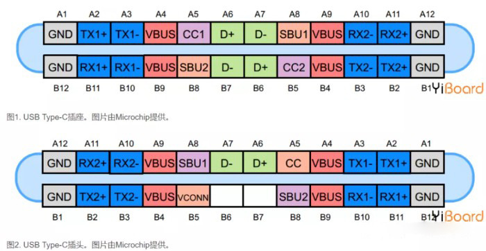
USB Type-C的PCB設計佈線要求

USB Type-C的供電和備用模式

使用USB Type-C標準的設備可以通過介面協商並選擇合適的功率。這些功率協商是通過稱為USB Power Delivery的協定實現的,該協定是上面CC線上的單線通信。下面的圖顯示了一個示例USB供電,其中接收器向源發送請求並根據需要調整VBUS電壓。首先,要求提供9 V匯流排。在源穩定匯流排電壓為9 V後,它會向接收器發送“電源就緒”消息。然後,接收器請求一個5V匯流排,並且源提供它並再次發送“電源就緒”消息,值得注意的是,“USB供電”不僅僅涉及與供電相關的談判,其他談判,例如與備用模式相關的協商,都是使用標準CC線上的供電協議完成的。

USB Type-C的CC1和CC2針腳

這些引腳是通道配置引腳。它們執行許多功能,例如電纜連線和移除檢測、插座/插頭方向檢測和當前廣播。這些引腳也可用於Power Delivery和Alternate Mode所需的通信。下面的圖顯示了CC1和CC2引腳如何顯示插座/插頭方向。在此圖中,DFP代表下游面向埠,該埠充當資料傳輸中的主機或電源。UFP表示上游面向埠,它是連接到主機或電力消費者的設備。DFP通過Rp電阻上拉CC1和CC2引腳,但UFP通過Rd將它們拉低。如果沒有連接電纜,則源在CC1和CC2引腳處看到邏輯高電平。連接USB Type-C電纜可創建從5V電源到地的電流路徑。由於USB Type-C電纜內只有一根CC線,因此只形成一條電流路徑。例如,在圖中,DFP的CC1引腳連接到UFP的CC1引腳。因此,DFP CC1引腳的電壓低於5 V,但DFP CC2引腳仍處於邏輯高電平。因此,監控DFP CC1和CC2引腳上的電壓,我們可以確定電纜連線及其方向。

除電纜方向外,Rp-Rd路徑還用作傳遞源電流能力資訊的方式。為此,功耗(UFP)監視CC線上的電壓。當CC線上的電壓具有其最低值(約0.41 V)時,源可以分別為USB 2.0和USB 3.0提供500 mA和900 mA的默認USB電源。當CC線電壓約為0.92 V時,源可提供1.5 A的電流。最高CC線電壓約為1.68 V,對應於3A的源電流能力

USB Type-C的VCONN引腳

USB Type-C旨在提供超快的資料傳輸速度以及高水準的功率。這些特徵可能需要使用通過在內部使用晶片進行電子標記的特殊電纜。此外,一些有源電纜利用重新驅動晶片來加強信號並補償電纜等引起的損耗。在這些情況下,我們可以通過施加5 V、1 W電源為電纜內部的電路供電提供給VCONN引腳。有源線纜使用Ra電阻來下拉CC2引腳。Ra的值與Rd不同,因此DFP仍然可以通過檢查DFP CC1和CC2引腳上的電壓來確定電纜方向。確定電纜方向後,與“有源電纜IC”對應的通道配置引腳將連接到5 V,1 W電源,為電纜內部的電路供電。例如,在下圖中,有效的Rp-Rd路徑對應於CC1引腳。因此,CC2引腳連接到VCONN表示的電源。


USB Type-C的SBU1和SBU2針腳&RX和TX引腳

SBU1和SBU2針腳

這兩個引腳對應於僅在備用模式下使用的低速信號路徑。

RX和TX引腳

有兩組RX差分對和兩組TX差分對。

這兩個RX對中的一個以及TX對可用於USB 3.0 / USB 3.1協議。由於連接器是可翻轉的,因此需要多工器通過電纜正確地重新路由所採用的差分對上的資料。

請注意,USB Type-C埠可以支援USB 3.0 / 3.1標準,但USB Type-C的最小功能集不包括USB 3.0 / 3.1。在這種情況下,USB 3.0 / 3.1連接不使用RX / TX對,並且可以被其他USB Type-C功能使用,例如備用模式和USB供電協定。這些功能甚至可以利用所有可用的RX / TX差分對。

USB Type-C的電源和接地引腳

VBUS和GND引腳是電源和信號的返回路徑。預設的VBUS電壓為5V,但標準允許器件協商並選擇VBUS電壓而不是預設值。最新的PD3.1的協議,電源傳輸允許VBUS具有高達48V的電壓,目前USB4最大電流也可以升高到5A。因此,USB Type-C可以提供240W的最大功率。當為諸如筆記型電腦的大型設備充電時,大功率是有用的。

USB Type-C的USB 2.0差分對

D +和D-引腳是用於USB 2.0連接的差分對。插座中有兩個D +引腳和兩個D-引腳。但是,這些引腳相互連接,實際上只有一個USB 2.0資料差分對可供使用。冗餘設計只是為了提供可翻轉的連接器。

Type-C相關產業鏈備受關注

Type C介面具有小巧纖薄、高速傳輸、正反可用、一口多用、供電提升等許多優勢,它的普及將是指日可待的。然而,這種Type C連接器產品必須在有限的空間內發揮做出更加精細化功能繁多的產品,而且必須承受較高的電流並進行高速資料傳輸,因此它的技術難度要求非常高,挑戰與機遇並存。


2023年12月23日 星期六

Modern USB gadget on Linux & how to integrate it with systemd

Modern USB gadget on Linux & how to integrate it with systemd (Part 1)

Andrzej Pietrasiewicz avatar

Andrzej Pietrasiewicz
February 18, 2019


Reading time: 10 minutes

tl;dr: Automate your gadget creation. A look at how to implement USB gadget devices on Linux machines which have the necessary UDC hardware, automate the manual configfs process via declarative gadget "schemes", and use systemd for gadget composition at boot time.

The big picture

In order to understand what is a USB gadget we need to have a look at a broader picture. In USB there are two distinct roles: a host and a device. The purpose of USB is to extend the host with some functionalities provided by devices: be it a mass storage device, an Ethernet card on USB, a sound card or the like. On a given USB bus there can be only one host and many (up to 127) devices. The bus is host-centric, which means that all the activities happening on it are decided and directed by the host.

One way of implementing a USB device is to have a machine running Linux, equipped with a special piece of hardware called USB Device Controller (UDC), and appropriate software running on it. It is exactly this case we will be talking about in this post.

Linux machine as a USB device

Hardware

The question you likely ask yourself is whether your machine has a UDC. In case of desktop PCs you most probably need a dedicated add-on card, which is not a very popular thing: there are not so many users who might want to convert their desktop PC into a USB device. But such boards do exist. The hardware supported by the Linux kernel can be found in drivers/usb/gadget/udc/Kconfig (line 306 in v5.0-rc6). In the embedded world a UDC is very often a part of your system-on-chip (SoC), but beware: merely having a UDC inside SoC does not mean that it is actually connected to anything on the board.

For example Raspberry Pi Zero's SoC does contain a UDC and it is connected to one of the micro USB sockets on the board. Other examples of suitably equipped boards are Odroid U3 and XU3, or Beagle Bone Black. If you don't have access to any hardware of this kind, fear not! You still can play (to some extent) with USB gadgets using an emulated UDC which is a part of the dummy_hcd kernel module. The dummy_hcd combines an emulated host controller with an emulated device controller, so your machine acts as both a USB host and a device. More on dummy_hcd will be in another blogpost which I'm going to write soon.

Oh, and one more thing: you can often come across the term OTG, which stands for on-the-go device and refers to chips which are capable of being either a host, or a device. For the purpose of this post we will be using the term UDC.

Software

The Linux kernel provides drivers for various UDCs. But merely being able to drive a UDC is not enough to fully implement a USB device. What is missing is actual functionality, for example mass storage or Ethernet over USB. And here comes what USB standard says: a USB device can provide more than one functionality over a single USB cable at a time. A set of such functionalities is called a configuration. In fact the standard allows more than one configuration - only one can be active at a time, though - but devices providing more than one are rarely seen in practice.

In the Linux kernel an implementation of a USB device is called a USB gadget. This implementation of gadgets is nicely layered: there is a so called composite layer, which contains code common for all USB functionalities and allows composing gadgets out of several functionalities. The composite layer talks to the UDC driver. On top of the composite driver there are USB functionalities (such as mass storage or Ethernet), which are called USB functions. We will be focusing on the composite layer and functions.

A modern USB gadget

The traditional approach to gadgets composition was to create a kernel module for a given composition of a gadget. And even if you wanted only a slightly different set of USB functions in your gadget, you had to create another kernel module. Around late 2012 a new approach started appearing. The idea was to decouple information about gadget composition from code and only provide building blocks out of which the user composes their gadget at runtime. Very much in the spirit of "mechanism, not policy" philosophy. The interface chosen for userspace interaction was configfs (by default can be found in /sys/kernel/config). After about two years, all USB functions available in the Linux kernel had been converted to use the new interface.

The usage pattern is like this: the user creates a separate directory per each gadget they want to have, gives their gadget a personality by specifying vendor id, product id and USB strings (visible e.g. after running lsusb -v as root), then under that directory creates the configurations they want and instantiates USB functions they want (both by creating respective directories) and finally associates functions to configurations with symbolic links. At this point gadget's composition is already in memory, but is not bound to any UDC. To activate the gadget one must write UDC name to the UDC attribute in the gadget's configfs directory - the gadget then becomes bound to this particular UDC (and the UDC cannot be used by more than one gadget). Available UDC names are in /sys/class/udc. Only after a gadget is bound to a UDC can it be successfully enumerated by the USB host.

A working, minimal example of ECM (Ethernet) on an Odroid U3, which leaves some attributes at their default values:

# go to configfs directory for USB gadgets
CONFIGFS_ROOT=/sys/kernel/config # adapt to your machine
cd "${CONFIGFS_ROOT}"/usb_gadget

# create gadget directory and enter it
mkdir g1
cd g1

# USB ids
echo 0x1d6b > idVendor
echo 0x104 > idProduct

# USB strings, optional
mkdir strings/0x409 # US English, others rarely seen
echo "Collabora" > strings/0x409/manufacturer
echo "ECM" > strings/0x409/product

# create the (only) configuration
mkdir configs/c.1 # dot and number mandatory

# create the (only) function
mkdir functions/ecm.usb0 # .

# assign function to configuration
ln -s functions/ecm.usb0/ configs/c.1/

# bind!
echo 12480000.hsotg > UDC # ls /sys/class/udc to see available UDCs

Please note that your vendor id is assigned for a fee by USB Implementors Forum (USB IF) - this refers to products you want to put on the market. For your own tinkering you can choose whatever you like. However, these ids (vendor and product) can be used by the host to decide which host-side driver to use to talk to your device. 0x1d6b is for Linux Foundation and 0x0104 is for Ethernet Gagdet. If your USB host sees such ids it assumes it needs the cdc_ether host-side driver.

If your device is connected to a Linux host, then you shoud see output similar to the below in host's dmesg:

usb 3-1.2.1.4.4: New USB device found, idVendor=1d6b, idProduct=0104
usb 3-1.2.1.4.4: New USB device strings: Mfr=1, Product=2, SerialNumber=3
usb 3-1.2.1.4.4: Product: ECM
usb 3-1.2.1.4.4: Manufacturer: Collabora
cdc_ether 3-1.2.1.4.4:1.0 usb0: register 'cdc_ether' at usb-0000:3c:00.0-1.2.1.4.4, CDC Ethernet Device, d2:c2:2d:b7:8e:6b

Note the Product and Manufacturer strings which are exactly what has been written to configfs.

A new usb interface should appear at the host side...

ifconfig -a

usb0: flags=4099<UP,BROADCAST,MULTICAST>  mtu 1500
        ether d2:c2:2d:b7:8e:6b  txqueuelen 1000  (Ethernet)
        RX packets 0  bytes 0 (0.0 B)
        RX errors 0  dropped 0  overruns 0  frame 0
        TX packets 1  bytes 90 (90.0 B)
        TX errors 0  dropped 0 overruns 0  carrier 0  collisions 0

# why not configure it?
ifconfig usb0 192.168.1.2 up

...and at the device:

ifconfig -a

usb0: flags=4098<BROADCAST,MULTICAST>  mtu 1500
        ether f2:40:e6:d3:01:2c  txqueuelen 1000  (Ethernet)
        RX packets 0  bytes 0 (0.0 B)
        RX errors 0  dropped 0  overruns 0  frame 0
        TX packets 0  bytes 0 (0.0 B)
        TX errors 0  dropped 0 overruns 0  carrier 0  collisions 0

# why not configure this one as well?
ifconfig usb0 192.168.1.3 up

# and ping the host?
ping 192.168.1.2
PING 192.168.1.2 (192.168.1.2) 56(84) bytes of data.
64 bytes from 192.168.1.2: icmp_seq=1 ttl=64 time=1.40 ms

Similarly, the device can be pinged from the host:

ping 192.168.1.3
PING 192.168.1.3 (192.168.1.3) 56(84) bytes of data.
64 bytes from 192.168.1.3: icmp_seq=1 ttl=64 time=1.06 ms

I want my modprobe g_ether back!

Poking around configfs is not difficult, but you need to know where to look, what to look for, what kind of directories to create and what values to write to particular files. And what to symlink from where. Creating a gadget containing just one function takes about 15-20 shell commands, which of course can be scripted. But it seems not a very nice approach. You can instead use an opensource tool called gt (https://github.com/kopasiak/gt) (requires https://github.com/libusbgx/libusbgx), which supports so called gadget schemes: instead of describing creating of your gadget procedurally (explicit shell commands) you describe it declaratively in a configuration file and the tool knows how to parse the file and do all the necessary configfs manipulation. This way modprobe g_ether can be changed to gt load my_ether.scheme, which is a very comparable amount of work :)

The scheme

A scheme corresponding to the above gadget is like this (let's call it ecm.scheme):

attrs : 
{
    idVendor = 0x1D6B;
    idProduct = 0x104;
};
strings = (
        {
                lang = 0x409;
                manufacturer = "Collabora";
                product = "ECM";
        }
);
functions : 
{
    ecm_usb0 : 
    {
        instance = "usb0";
        type = "ecm";
    };
};
configs = ( 
    {
        id = 1;
        name = "c";
        functions = ( 
            {
                name = "ecm.usb0";
                function = "ecm_usb0";
            } );
    } );

Now at the device side you can simply:

gt load ecm.scheme g1 # load the scheme and name the gadget 'g1'

and achieve the same gadget composition as with the above shell commands.

And systemd?

systemd is here. I'm not going to discuss whether it is a good thing or a bad thing. Instead, I want to share with you how you can have systemd compose your gadget, for example at system boot time. A typical example is to have your Ethernet connection over USB up and running and you want that controllable by systemd, so that you for example can systemctl enable/disable your gadget.

The event

The obvious event triggering our gadget creation is the appearance of a UDC in the system. https://github.com/systemd/systemd/issues/11587 points to a pull request, which adds a new udev rule for systemd:

SUBSYSTEM=="udc", ACTION=="add", TAG+="systemd", ENV{SYSTEMD_WANTS}+="usb-gadget.target"

The rule triggers reaching the usb-gadget.target, whose purpose is to mark the point when UDC is available and allow other units depend on it:

[Unit]
Description=Hardware activated USB gadget
Documentation=man:systemd.special(7)

The service

Now that we have a target to depend on, we can create a service which will be started once the target is reached. Let's call it usb-gadget.service.

[Unit]
Description=Load USB gadget scheme
Requires=sys-kernel-config.mount
After=sys-kernel-config.mount

[Service]
ExecStart=/bin/gt load ecm.scheme ecm
RemainAfterExit=yes
ExecStop=/bin/gt rm -rf ecm
Type=simple

[Install]
WantedBy=usb-gadget.target

Such a service can be controlled with systemctl:

systemctl enable usb-gadget.service
systemctl disable usb-gadget.service

This way the usb-gadget.target can be reached with or without actually composing the gadget, or a different gadget can be chosen by the system administrator for each purpose.

I want my own USB function!

The selection of USB functions available for composition is quite large (20), but you still might need something else, for example some custom USB protocol. Or, even not so custom (such as e.g. ptp), but a protocol which is not likely to reach upstream kernel. What to do? FunctionFS to the rescue! I will talk about that in the next installment of this post, so stay tuned.


Modern USB gadget on Linux & how to integrate it with systemd (Part 2)

Andrzej Pietrasiewicz avatar

Andrzej Pietrasiewicz
March 27, 2019


Reading time: 10 minutes

In the previous post I introduced you to the subject of USB gadgets implemented as machines running Linux. We also talked about modern style of USB gadget creation and integrating that with systemd. In this post, we look at how to implement your very own USB function with FunctionFS and how to integrate that with systemd.

The general idea of FunctionFS

The idea is to delegate actual USB function implementation to userspace, using a filesystem interface (read()/write() etc). This way, USB out traffic (from host) is available at a file descriptor ready for reading, and USB in traffic (to host) is accepted at a file descriptor ready for writing.

What you need to know before using FunctionFS

In USB all communication is performed through so called endpoints. At the device side the endpoints are (hardware) FIFO queues associated with the UDC. There are 4 types of USB endpoints: control, bulk, iso and interrupt

  • Control endpoint is endpoint 0 and all USB devices shall have at least endpoint 0. This is a bi-directional communication channel between the host and the device used for enumerating and then controlling the device - remember, the USB is a host centric bus. So even if a device has some new data to be sent to the host it is the host that actually asks for data and the communication required to arrange this happens on the endpoint 0. All other types of endpoints are uni-directional
  • Bulk endpoints are meant for tansferring (potentially) large amounts of data on a "best effort" basis, that is, as available bandwith allows, so there are no timing guarantees for bulk data. On the other hand bulk data is guaranteed to be transmitted error-free (perhaps using re-transmission under the hood). 
  • Iso(chronous) endpoints are meant for time-sensitive data (such as audio or video) with guaranteed bandwitdh and bounded latency. Neither data delivery nor integrity is guarenteed, though, and it is on purpose: in multimedia transmission much more harm is done by non-timely data delivery rather than by occasional non-integrity or even loss of a frame. 
  • Interrupt endpoints are for non-periodic data transfers "initiated" by the device (such as mouse movements or keystrokes) and have guaranteed latency. The "initiation" by the device is in fact queuing the data on an endpoint, and then the host polls it when it considers appropriate. In USB it's a host's world. Get used to it or quit using USB.

Why am I telling you this? You need to know that each USB function requires its own set of endpoints, which must not be used at the same time by any other function. This makes UDC's endpoints a scarce resource and imposes a limit on a number of functions which can be provided by your gadget at a time (in one configuration, but you can "overcommit" by specifying multiple configurations - you still remember, that only one of them can be active at a time?). If you want to roll your own USB function, you need to know how many and what kind of endpoints you need, and, especially if you want to compose it with other functions, whether the number of available endpoints is not exceeded. Modern UDCs usually do provide enough endpoints to compose 2-3 moderately "endpoint-hungry" functions into one configuration without any problems.

More detailed idea of FunctionFS

Now that you know about endpoints, you can learn more about FunctionFS. From the point of view of the gadget it is yet another USB function available for composing a gadget from. But it is special, because each instance of FunctionFS provides an instance of a 'functionfs' filesystem to be mounted. If you mount it you will notice there is only one entry: ep0. Its name suggests it is associated with endpoint 0. Indeed it is. However, the good news is that you don't need to implement all the endpoint 0 handling, because most of that is already taken care of for you by the composite layer. You only need to handle control requests directed at your particular USB function. ep0 is also (ab)used to specify the endpoints and USB strings. FunctionFS is not considered ready for binding until endpoint descriptors and strings are written to ep0. The gadget as a whole is not ready for binding if any of its functions is not ready. After the descriptors and strings are written, FunctionFS creates appropriate number of ep<number> files for you to use to implement the desired data streams between the host and the device.

An example function can be found in kernel sources: tools/usb/ffs-test.c The file also contains an example of how to specify USB descriptors and strings to be written to ep0 to make FunctionFS ready. Actually I'm using its modified and simplified version, which passes to the host whatever the host writes to it. We will get to its code later in this post.

And how to integrate THAT with systemd?

Compared to the previous scenario there are more steps involved before the gadget becomes operational:

  • load gadget scheme and don't enable yet (because it contains FunctionFS)
  • mount FunctionFS instance
  • write descriptors and strings
  • start the userspace daemon (e.g. ffs-test)
  • enable the gadget (now that it's ready, bind it to UDC)

It turns out that systemd already has means to automate writing the descriptors and strings to FunctionFS, and starting a userspace daemon! However, the remaining steps need to be taken care of.

The scheme

Let's call the scheme ffs_test.scheme. It describes a minimal gadget with FunctionFS, leaving some attributes at their default values:

    attrs : 
    {
        idVendor = 0xABCD;
        idProduct = 0x1234;
    };
    strings = ( );
    functions : 
    {
        ffs_loopback : 
        {
            instance = "loopback";
            type = "ffs";
        };
    };
    configs = ( 
        {
            id = 1;
            name = "c";
            functions = ( 
                {
                    name = "ffs.loopback";
                    function = "ffs_loopback";
                } );
        } );

One important thing to note is that the instance name (here: "loopback") becomes a "device" name to be used when mounting this FunctionFS instance.

The service

Let's call our example service unit usb-gadget-ffs.service. This unit is almost identical to the usb-gadget.service, except the ExecStart line:

ExecStart=/bin/gt load -o ffs_test.scheme ffs_test

The difference is that we tell gt to only (-o) load gadget's composition but not bind it, which would fail anyway because the FunctionFS instance is not ready yet.

Another difference is that the Type cannot be "simple" this time, because we need systemd not to schedule loading of dependent modules until gadget scheme is fully loaded - and, consequently, FunctionFS instance registered and made available for mounting. Units of type "simple" are considered completely run immediately, so we need to change to:

Type=oneshot

This change ensures that the dependent modules will be started only after full completion of the gt command.

Complete usb-gadget-ffs.service code:

[Unit]
Description=Load USB gadget scheme
Requires=sys-kernel-config.mount
After=sys-kernel-config.mount

[Service]
ExecStart=/bin/gt load -o ffs_test.scheme ffs_test
RemainAfterExit=yes
ExecStop=/bin/gt rm -rf ffs_test
Type=oneshot

[Install]
WantedBy=usb-gadget.target

The mount

We can use a mount unit to automatically mount our FunctionFS instance. We choose to mount it at /run/ffs_test, so the mount unit must be named run-ffs_test.mount:

[Unit]
Description=Mount FunctionFS instance
Requires=usb-gadget-ffs.service
After=usb-gadget-ffs.service
Before=ffs.socket

[Mount]
# "device" name (FunctionFS instance name)
What=loopback
Where=/run/ffs_test
Type=functionfs
Options=defaults
TimeoutSec=5

[Install]
WantedBy=usb-gadget.target

and then use systemctl enable run-ffs_test.mount

The above two units are enough to load our gadget composition into memory at UDC's appearance and mount its accompanied FunctionFS instance.

Descriptors, strings and the userspace daemon

systemd supports socket units capable of listening to usb traffic directed at FunctionFS. Such a socket unit must be pointed at an already mounted FunctionFS instance. The socket unit contains ListenUSBFunction entry in its [Socket] section to specify exactly that. It also contains a Service entry pointing to the service unit associated with this unit and such a socket unit must have its associated service unit.

When the socket unit is started, it starts its associated service unit, which contains USBFunctionDescriptors and USBFunctionStrings entries. The two specify locations of files containing binary blobs representing USB descriptors and strings, respectively. The service unit's job is then to write those to ep0 of the corresponding FunctionFS instance. And here the systemd's lazy daemon start comes into play: the descriptors and strings are already passed to FunctionFS, so it becomes ready _but_ the daemon is _not_ started until some traffic directed at this FunctionFS instance happens on USB. And it is exactly the job of the socket unit to make it work. The daemon binary is specified with the usual ExecStart entry in the service unit.

The socket unit

Let's call it ffs.socket:

[Unit]
Description=USB function fs socket
Requires=run-ffs_test.mount
After=run-ffs_test.mount
DefaultDependencies=no

[Socket]
ListenUSBFunction=/run/ffs_test
Service=functionfs-daemon.service
# we will get to ExecStartPost later
ExecStartPost=/bin/gt enable ffs_test

[Install]
WantedBy=usb-gadget.target

And then systemctl enable functionfs.socket.

The service unit accompanying the socket unit

We call it functionfs-daemon.service as per the Service entry above.

[Service]
ExecStart=/root/bin/ffs-test
USBFunctionDescriptors=/root/descriptors-ffs-test.bin
USBFunctionStrings=/root/strings-ffs-test.bin

A question you likely ask yourself is where to get the .bin files from? include/uapi/linux/usb/functionfs.h in the kernel sources provides the format description (line 89 in v5.0-rc6). It is up to you how you create these blobs. An example of how to create the descriptors (and strings) in a C program can be found in tools/usb/ffs-test.c. Please note that you are supposed to use usb_functionfs_descs_head_v2, because the other format is now deprecated. You can modify the program so that it doesn't do anything except writing the descriptors/strings to standard output and then capture the result in a file.

Here is a hex dump of descriptors and strings blobs for a high-speed-only example funtion:

# hd descriptors-ffs-test.bin 
00000000  03 00 00 00 27 00 00 00  02 00 00 00 03 00 00 00  |....'...........|
00000010  09 04 00 00 02 ff 00 00  01 07 05 81 02 00 02 00  |................|
00000020  07 05 02 02 00 02 01                              |.......|
00000027

# hd strings-ffs-test.bin 
00000000  02 00 00 00 1d 00 00 00  01 00 00 00 01 00 00 00  |................|
00000010  09 04 55 53 42 20 46 69  6c 74 65 72 00           |..USB Filter.|
0000001d

Please note that the descriptors are created only in the unmodified version of ffs-test.c. As promised, we will get to the modified version later in this post.

Enabling the gadget

If the functionfs.socket did not contain the ExecStartPost entry, then at this point we would have a gadget ready to be bound, but not actually bound. The ExecStartPost contains a command which executes our gadget binding _after_ the service unit is started, which is the last missing piece in this puzzle. Your gadget is now composed and activated with systemd.

Can I use existing daemon code to integrate with systemd?

No, you can't. However, usually patching userspace code to be able to be passed open file descriptors by systemd is a trivial task. And to make it even easier for you to play with FunctionFS and systemd I have modified the ffs-test.c program for using with systemd (it purposedly contains some simplifications in order for you to be able to follow the code easily, so you can't take it as a full-fledged implementation):

https://gitlab.collabora.com/andrzej.p/ffs-systemd/tree/ffs-systemd

look for tools/usb/ffs-test.c on the ffs-systemd branch.

Giving it a try

In order to test the above mentioned modified function you need the following:

  • Scheme of the example gagdet from this post
  • All systemd units from this post
  • ffs-test binary compiled from the modified sources
  • FunctionFS endpoint descriptors and strings binary blobs
  • usbserial module at host with generic serial support

Set up your gadget and connect it to the host, it should enumerate correctly. The idea is to bind generic usb serial driver at the host to our device. This results in automatic creation of ttyUSB<X> at the host side. And then whatever you write to the ttyUSB<X> you can read back from it. That's what the modified ffs-test.c does - a loopback function.

# at the host
echo 0xabcd 0x1234 > /sys/bus/usb-serial/drivers/generic/new_id

dmesg
<...>
usbserial_generic 3-1.2.1.4.3:1.0: The "generic" usb-serial driver is only for testing and one-off prototypes.
usbserial_generic 3-1.2.1.4.3:1.0: Tell linux-usb@vger.kernel.org to add your device to a proper driver.
usbserial_generic 3-1.2.1.4.3:1.0: generic converter detected
usb 3-1.2.1.4.3: generic converter now attached to ttyUSB1

while true; do dd if=/dev/ttyUSB1 bs=1 iflag=nocache status=none 2>/dev/null; done

And still at the host, at some other console:

man -P cat bash > /dev/ttyUSB1

The contents of bash man page should appear at the console where the "while" loop runs. You can further modify ffs-test.c to e.g. capitalize all the letters, or use some encryption algorithm to cipher your text, effectively creating a hardware crypto device on USB!

What's next?

In the next installment I will write about using dummy_hcd. And in yet another one we will add some systemd templatization to make the above solutions more generic.