For MDM9150
PC5 does not need SIM for calibration
UU needs SIM for calibration
Q1. "Filter in front of LNA" vs "LNA in front of filter"
A1. "LNA in front of filter" (w/ proper frequency response) provides better RF performance.
Q2. PA linearity index?
Q3. Spectrum Analyzer : Resolution BW vs Video BW
A3. Resolution BW : frequency axis grid
Video BW : displayed spectrum is low-pass filtered.
Q4. Btwn TDD and FDD, which requires higher quality power supply? why?
(same Fc, BW, 64QAM and peak power)
A4. FDD. Higher power supply helps inter band seperation.
Source https://www.itsfun.com.tw/BPDU/wiki-8372865-1834445
網橋協定資料單元(Bridge Protocol Data Unit)。是一種生成樹協定問候封包,它以可配置的間隔發出,用來在網路的網橋間進行信息交換。
當一個網橋開始變為活動時,它的每個連線埠都是每2s(使用缺省定時值時)傳送一個BPDU。然而,如果一個連線埠收到另外一個網橋傳送過來的BPDU,而這個BPDU比它正在傳送的BPDU更優,則在地連線埠會停止傳送BPDU。如果在一段時間(缺省為20s)後它不再接收到鄰居的更優的BPDU,則在地連線埠會再次傳送BPDU。
BPDU是網橋協定資料單元(Bridge Protocol Data Unit)的英文首字母縮寫。
協定ID:該值總為0。
版本號:STP的版本(為IEEE 802.1d時值為0)。
報文類型:BPDU類型(配置BPDU=0,TCN BPDU=80)。
標記域:LSB(最低有效位)=TCN標志;MSB(最高有效位)=TCA標志。
根網橋ID:根信息由2位元組優先權和6位元組ID組成。這個信息組合標明已經被選定為根網橋的設備標識。
根路徑成本:路徑成本為到達根網橋交換機的STP開銷。表明這個BPDU從根網橋傳輸了多遠,成本是多少。這個欄位的值用來決定哪些連線埠將進行轉發,哪些連線埠將被阻斷。
傳送網路橋ID:傳送該BPDU的網橋信息。由網橋的優先權和網橋ID組成。
連線埠ID:傳送該BPDU的網橋連線埠ID。
計時器:計時器用于說明生成樹用多長時間完成它的每項功能。這些功能包括報文老化時間、最大老化時間、訪問時間和轉發延遲。
最大老化時間:根網橋傳送BPDU後的秒數,每經過一個網橋都會增加1,所以它的本質是到達根網橋的跳計數。
訪問時間:根網橋連續傳送BPDU的時間間隔。
轉發延遲:網橋在監聽學習狀態所停留的時間。
BPDU究竟是如何工作的呢?
這得從網橋說起。網橋有三種典型的方式:透明橋、源路由橋與源路由透明橋。
網橋典型地連線兩個用同樣介質存取控製方法的網段,IEEE 802.1d規範(此規範是為所有的802介質存取方法開發的)定義了透明橋。源路由橋是由IBM公司為它的令牌環網路開發的;而源路由透明橋則是透明橋和源路由橋的組合。橋兩邊的網段分屬于不同的沖突域,但卻屬于同一個廣播域。
在一個橋接的區域網路裏,為了增強可靠性,必然要建立一個冗餘的路徑,網段會用冗餘的網橋連線。但是,在一個透明橋橋接的網路裏,存在冗餘的路徑就能建立一個橋回路,橋回路對于一個區域網路是致命的。
生成樹協定是一種橋嵌套協定,在IEEE 802.1d規範裏定義,可以用來消除橋回路。它的工作原理是這樣的:生成樹協定定義了一個封包,叫做橋協定資料單元BPDU(Bridge Protocol Data Unit)。網橋用BPDU來相互通信,並用BPDU的相關機能來動態選擇根橋和備份橋。但是因為從中心橋到任何網段隻有一個路徑存在,所以橋回路被消除。
在一個生成樹環境裏,橋不會立即開始轉發功能,它們必須首先選擇一個橋為根橋,然後建立一個指定路徑。在一個網路裏邊擁有最低橋ID的將變成一個根橋,全部的生成樹網路裏面隻有一個根橋。根橋的主要職責是定期傳送配置信息,然後這種配置信息將會被所有的指定橋傳送。這在生成樹網路裏面是一種機製,一旦網路結構發生變化,網路狀態將會重新配置。
當選定根橋之後,在轉發封包之前,它們必須決定每一個網段的指定橋,運用生成樹的這種演算法,根橋每隔2秒鍾從它所有的連線埠傳送BPDU包,BPDU包被所有的橋從它們的根連線埠復製過來,根連線埠是接根橋的那些橋連線埠。BPDU包括的信息叫做連線埠的COST,網路管理員分配連線埠的COST到所有的橋連線埠,當根橋傳送BPDU的時候,根橋設定它的連線埠值為零。然後沿著這條路徑,下一個橋增加它的配置連線埠COST為一個值,這個值是它接收和轉發封包到下一個網段的值。這樣每一個橋都增加它的連線埠的COST值為它所接收的BPDU的包的COST值,所有的橋都檢測它們的連線埠的COST值,擁有最低連線埠的COST值的橋就變為了指定的橋。擁有比較高連線埠COST值的橋置它的連線埠進入阻塞狀態,變為了備份橋。在阻塞狀態,一個橋停止了轉發,但是它會繼續接收和處理BPDU封包。
Source http://smalleaf.blogspot.com/2011/10/switch-bpdu-guard.html
防止私接Switch的利器 - BPDU GUARD
今天客戶問我一個問題:
Source https://a46087.pixnet.net/blog/post/32217254
======================================================================
|
網孔底 |
Hub |
NB / Win10 / WiFi/Ethernet network bridge
by following https://superuser.com/questions/1319833/use-wifi-and-ethernet-simultaneously-on-windows-10 |
|
PC / Linux / Ethernet |
Source https://stackoverflow.com/questions/942273/what-is-the-ideal-fastest-way-to-communicate-between-kernel-and-user-space
mmap
system calls
ioctls
/proc & /sys
netlink
Source https://magicjackting.pixnet.net/blog/post/113860339
Reentrant vs Thread-safe
Reentrancy 和 thread-safty 是兩個容易被搞混了的觀念. 其中最嚴重的是誤以為 reentrant function 必定是 thread-safe 或者相反以為 thread-safe function 必為 reentrant, stackoverflow 網站上的答覆甚至同時出現二種答案的現象.
首先來看 reentrancy: 字面上的意思是可重入. Reentrancy 原先是討論單一執行緒環境下 (即沒有使用多工作業系統時) 的主程式和中斷服務程式 (ISR) 之間共用函數的問題. 當然現在多核心的 CPU 盛行, 討論範圍也必需擴充至多執行緒的情況. 重點是它討論的主體是: 在 ISR 中使用的函數 (不論是自己寫的或者是函數庫提供的) 是否會引發錯誤結果. 主要的達成條件是二者 (ISR 和非 ISR) 的共用函數中不使用靜態變數或全域變數 (意即只用區域變數). 一般是撰寫驅動程式 (device driver) 或者是寫 embedded system 的人會遇到這個問題.
再來是 thread-safety: 字面上的意思是執行緒 (線程) 安全. Thread-safe 一開始就針對多執行緒的環境 (CPU 可能單核也可能是多核), 討論的是某一段程式碼在多執行緒環境中如何保持資料的一致性 (及完整性), 使不致於因為執行緒的切換而產生不一致 (及不完整) 或錯誤的結果. 所以是程式中有運用到多執行緒的大型應用系統的程式人員會比較常遇到這類問題. 問題的產生點一般出現在對某一共用變數 (或資源) 進行 read-modify-write (或者類似的動作(註一)) 時, 還沒來得及完成整個動作, 就被其他的執行緒插斷, 並且該執行緒也一樣對這個共用變數 (或資源) 進行 read-modify-write (或者類似的動作). 例如Thread1 和 Thread2 之間我們需要一個作為計數器的共用變數:
'\r'是回車,前者使游標到行首,(carriage return)ASCII碼(0x0D)
'\n'是換行,後者使游標下移一格,(line feed)ASCII碼(0xoA)Source: https://www.trustonic.com/technical-articles/comparing-the-tee-to-integrated-hsms/
As more and more devices become connected so the need for ever greater security and protection of critical assets increases. Traditionally such support has been provided by a Hardware Security Module (HSM) but over the last decade the use of Trusted Execution Environments (TEE) has grown significantly. This article aims to provide the reader with an understanding of the difference between these two solutions and their suitability for different scenarios.
Generically, a HSM provides key management and cryptographic functionality for other applications.
A TEE also provides this functionality, along with enabling application (or security focused parts of applications) to execute inside its isolation environment.
For example, in modern Android mobile devices, the TEE is already unknowingly used every day, by millions of people as an HSM equivalent, through the use of a Trusted Application (TA) providing the Android KeyMaster functionality.
Regular Execution Environment (REE) is the term in the TEE community for everything in a device that is outside a particular TEE. Technically, from a particular TEEs point of view, all components that are outside of its security boundary live in the REE. Having said that, for simplification of the big picture, a device with multiple TEEs, SIMs, HSMs or other high trust components, may have those separated out from the REE. The REE houses the Regular OS, which in combination with the rest of that execution environment, does not have sufficient security to meet a task needed by the device.
For more background on terminology like TEE and REE please have a look in “What is a TEE?”
For more information on the ARM TrustZone hardware security behind the TEE have a look in “What is a TrustZone?”
In compact devices with integrated HSM, the software architecture looks something like this:
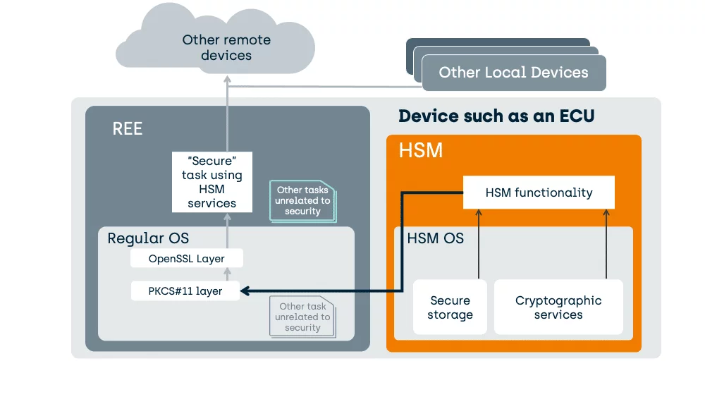
The HSM provides Cryptographic Services to your security focused task.
The “Secure” task in the REE has data. The HSM can receive that data and encrypt or decrypt that data, before handing it back to the issuer task in the REE.
Here is how we support HSM functionality in a TEE enabled device today:
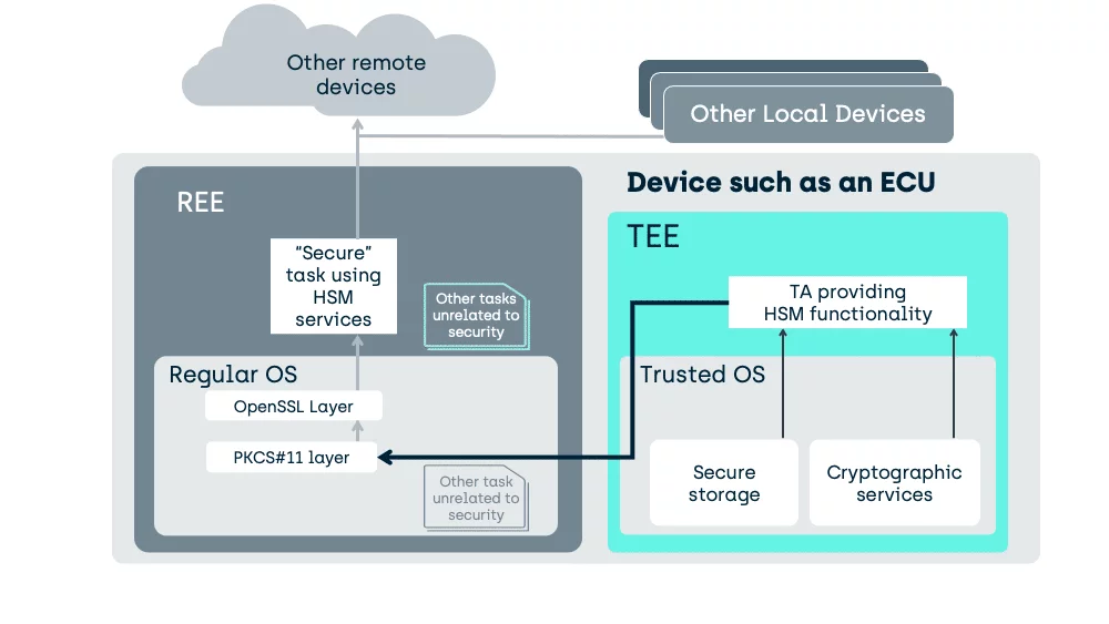
In an Android device, the above HSM will typically be replaced by a TA, within the TEE, implementing Keymaster functionality and an Android specific REE stack rather than OpenSSL/PKCS#11.
In the above case, with a simpler Regular OS as might be found in an Engine Control Unit (ECU), a generic TA has been specifically written to provide the functionality of a typical HSM.
A TEE need not be used as a fixed purpose service provider like an HSM, it can also host the tasks directly.
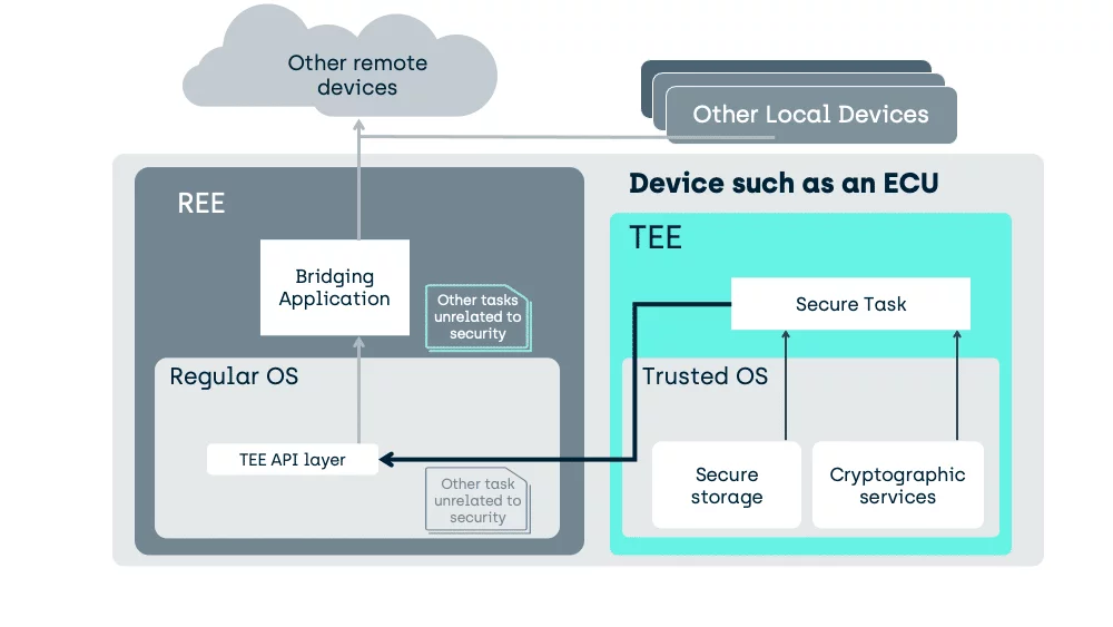
Here we move the task into the TEE and manipulation of the unencrypted data can occur, in a place inaccessible to activity in the REE.
As an example of what we gain:
Some HSMs can load code to execute through proprietary extensions, but a GlobalPlatform compliant TEE uses standardised interfaces, enabling tasks developed for one TEE, to execute on another. Such tasks, executing in the TEE, are called “Trusted Applications”.
HSM’s cannot directly protect the I/O ports providing sensor data, or controlling actuators, from software attacks in, for example, the REE of the ECU of a vehicle.
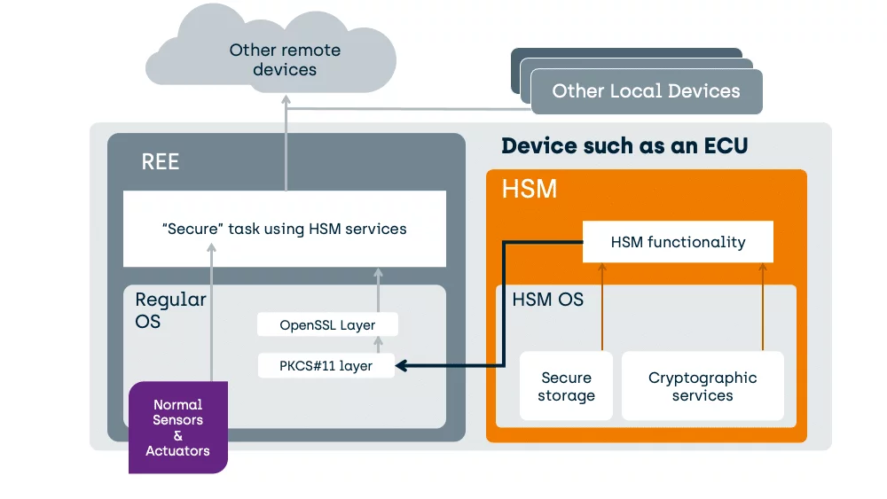
Unlike an HSM, on a correctly designed System-On-Chip (SoC) a TEE can also interface to peripherals. This enables the creation of a secure task, housed safely inside the TEE, that can be used to substantially enhance the critical tasks’ security.
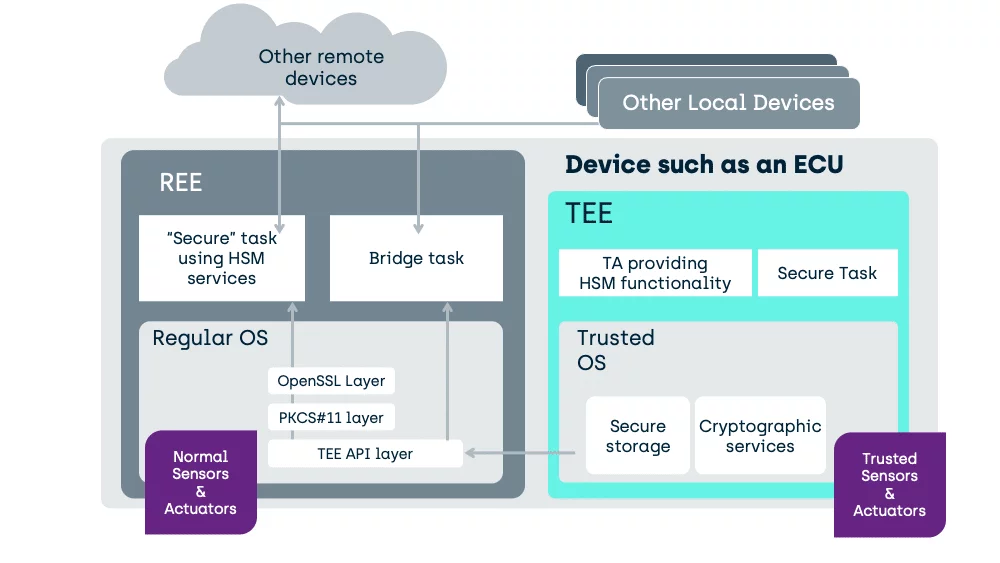
Well, consider an example, from the automotive industry, of a fuel throttle. If the throttles’ I/O control port on the ECU is exposed in the REE software then it does not matter how much security the REE “Secure” task use of the HSM brings; you would not be using an HSM if you had high confidence in the security of the REE itself, and so you cannot have confidence that the software in the REE cannot be attacked.
If the REE is open to attack, that means that attacked REE software can potentially gain unauthorised access to that I/O port, no matter how good the HSM is.
In the TEE (like in an HSM), we do not have the generic load of software tasks unrelated to security. A task in the TEE can interface to hardware control ports without risk of other software making unauthorised access.
If I only have an HSM in the above example, then all I can do is protect the data traffic to a device, not the decision making in the device. With a TEE, I can do both.
As we have seen above, one issue with the use of an HSM is the exposure of data communications before any encryption has occurred.
Fundamentally, device integrated HSMs might go as far as to use on-SoC hardware methods to protect their keys from extraction that are stronger than those of a TEE. However, the method to transfer data to the HSM for protection by those keys is no more strongly protected, than that used by a TEE and can be far weaker.
Consider the following PCB-attached HSM in comparison to a typical TEE which will be using a stacked die (Package on a Package) to protect its much higher speed traffic:
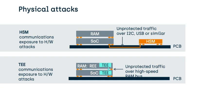
Stronger TEEs do not even use external RAM, as shown above, but can use on-SoC RAM instead.

In this case, the benefit of using a TEE to provide traditional HSM functionality is a significant reduction in the exposure of unprotected data and therefore an enhancement of the overall security for the platform.
Ultimately, if you are concerned about key extraction, it is advised that designs keep the key batch size small, whether using a TEE or an HSM.
It is worth noting that in the EVITA standards, some HSM types reside on the same SoC as the REE, but in those cases their hardware protection methods are typically the same as a TEE (see the EVITA HSM levels).
In fast moving new innovation areas, such as connected vehicles and robotics, as well as consumer electronics devices, a TEE provides a cost effective and future proofed alternative to using an HSM.
In addition to the potential of providing typical HSM functionality, a GlobalPlatform compliant TEE can also protect the critical tasks directly and has standardised methods for enabling over-the-air updating of critical systems.
Fundamentally, a typical HSM is an attack-resistant cryptographic device designed to perform a specific set of cryptographic functions by the HSM designer. It provides the confidence of non-interference inside the scope defined by the relevant protection profile. A standardised TEE can do the same, and significantly more without the need to add additional hardware. As the TEE resides on the existing SoC integrated MMUs and TrustZone enabled hardware, the overall hardware bill of materials can be reduced and as components are being removed, and incidentally reducing risks of hardware failure.
The development of TEEs is driven by standards, such as GlobalPlatform, and this brings predictability and interoperability. This means that device OEMs and third parties, can develop Trusted Applications to support an ever-growing list of platform security requirements.