2018年7月24日 星期二

server certificate verification failed. CAfile: /etc/ssl/certs/ca-certificates.crt CRLfile: none

Source : https://stackoverflow.com/questions/21181231/server-certificate-verification-failed-cafile-etc-ssl-certs-ca-certificates-c#

TLDR:
hostname=XXX
port=443
trust_cert_file_location=`curl-config --ca`

sudo bash -c "echo -n | openssl s_client -showcerts -connect $hostname:$port \
    2>/dev/null  | sed -ne '/-BEGIN CERTIFICATE-/,/-END CERTIFICATE-/p'  \
    >> $trust_cert_file_location"
Long answer
The basic reason is that your computer doesn't trust the certificate authority that signed the certificate used on the Gitlab server. This doesn't mean the certificate is suspicious, but it could be self-signed or signed by an institution/company that isn't in the list of your OS's list of CAs. What you have to do to circumvent the problem on your computer is telling it to trust that certificate - if you don't have any reason to be suspicious about it.
You need to check the web certificate used for your gitLab server, and add it to your 
/bin/curl-ca-bundle.crt.
To check if at least the clone works without checking said certificate, you can set:
export GIT_SSL_NO_VERIFY=1
#or
git config --global http.sslverify false
But that would be for testing only, as illustrated in "SSL works with browser, wget, and curl, but fails with git", or in this blog post.
Check your GitLab settings, a in issue 4272.

To get that certificate (that you would need to add to your curl-ca-bundle.crt file), type a:
echo -n | openssl s_client -showcerts -connect yourserver.com:YourHttpGilabPort \
  2>/dev/null  | sed -ne '/-BEGIN CERTIFICATE-/,/-END CERTIFICATE-/p'
(with 'yourserver.com' being your GitLab server name)
To check the CA (Certificate Authority issuer), type a:
echo -n | openssl s_client -showcerts -connect yourserver.com:YourHttpGilabPort \
  2>/dev/null  | sed -ne '/-BEGIN CERTIFICATE-/,/-END CERTIFICATE-/p' \
  | openssl x509 -noout -text | grep "CA Issuers" | head -1

to identify the location of curl-ca-bundle.crt, you could use the command
curl-config --ca

Also, see my more recent answer "github: server certificate verification failed": you might have to renistall those certificates:
sudo apt-get install --reinstall ca-certificates
sudo mkdir /usr/local/share/ca-certificates/cacert.org
sudo wget -P /usr/local/share/ca-certificates/cacert.org http://www.cacert.org/certs/root.crt http://www.cacert.org/certs/class3.crt
sudo update-ca-certificates
git config --global http.sslCAinfo /etc/ssl/certs/ca-certificates.crt
Handbook - Ubuntu FireWall (ufw)

原文: https://webcache.googleusercontent.com/search?q=cache:dWjisuVtSoQJ:https://www.phpini.com/linux/ubuntu-firewall-ufw+&cd=1&hl=zh-TW&ct=clnk&gl=tw

ufw (Uncomplicated Firewall) 是 Ubuntu 內建的防火牆配置工具, ufw 使用上十分簡單, 以下是使用 ufw 的簡單例子:
檢查防火牆目前狀態:
$ sudo ufw status verbose
開啟 TCP 埠號 22 對外連線:
$ sudo ufw allow 22/tcp
開啟 TCP 埠號 80 及 443 對外連線, 可以直接用 http 及 https 表示:
$ sudo ufw allow http
$ sudo ufw allow https
或者直接輸入埠號也可以:
$ sudo ufw allow 80/tcp
$ sudo ufw allow 443/tcp
開啟 TCP 及 UDF 埠號 53 對外連線:
$ sudo ufw allow 53
只准許特定 IP (例如 192.168.0.10)連接埠號 22:
$ sudo ufw allow from 192.168.0.10 to any port 22
允許 192.168.0.0/24 網段存取 Samba 服務
$ ufw allow from 192.168.1.0/24 to any app Samba
列出服務使用埠號詳情:
$ sudo ufw app list

Howto install Google Chrome in Linux ?

Source: https://askubuntu.com/questions/510056/how-to-install-google-chrome

google-chrome-stable is available on a 3rd Party Repository: Google Chrome (for Stable).
Follow the instruction for installation:
  1. Add Key:
    wget -q -O - https://dl-ssl.google.com/linux/linux_signing_key.pub | sudo apt-key add -
  2. Set repository:
    echo 'deb [arch=amd64] http://dl.google.com/linux/chrome/deb/ stable main' | sudo tee /etc/apt/sources.list.d/google-chrome.list
  3. Install package:
    sudo apt-get update 
    sudo apt-get install google-chrome-stable

USB Battery Charge Specification - BC 1.2

原文: http://www.cash.idv.tw/wordpress/?p=8334

目前 USB 的充電規範以 USB應用者論壇(USB-IF) 所制定 BC (Battery Charge Spec.) 1.2 為主, 它定義了每個類型充電器的可用電流上限, 以及充電器的類型.
原先大家的認知, 都是 USB 要支援 500mA 的電流. 但是實際上, 這種電流可能連外接硬碟都推不動. 於是大家可能都 "偷偷" 可以供到 1A. 從 BC 1.1 開始, 規範中就直接讓 USB 可以輸出 1.5 A 了.
在充電類型方面, 一共有三種定義:標準下行埠(Standard Downstream Port, SDP)、充電下行埠(Charging Downstream Port, CDP)及專用充電埠(Dedicated Charging Port, DCP). 
所謂的 SDP 就是標準的 USB HUB 輸出, 像是電腦或是螢幕基座上的 USB 輸出大抵都支援 SDP. 它的充電電流是 500 mA, 所以不致於充得太快! 甚至在被充電裝置完全沒電時, 可以先用 100m A 的小電流輸出, 等到充至 0.5~0.7 V 時才改回 500 mA.
這有什麼好處呢?如果沒有人在管電流限額, 而沒電的手機電壓已經趨近於 0 了, 當輸入阻抗很小, 那麼電流將會很大, 使得溫度過高, 說不定會燒壞什麼電路. 阻抗給很大, 那麼電流就會太小, 導致充得很慢. 因此, 聰明的控制電流是有必要的.
至於 CDP 可以提供 500mA 和 1.5A 兩種電流, 算是有 "兩下子" 的 USB 接口. 一般會先用 500mA, 若是符合 1.5A 的快充, 就會切換過去 [3, 4].
最後的 DCP 只能充電, 不能傳 data.
上面提到的都是 USB 2.0, 而一般 USB 3.0 都是用 USB 2.0 的規範充電. 特別強調 USB 3.0 充電的話, 指得是 BC 1.2, 特別是 DCP 快充 [5].
USB 可持裝置 (portable device, 簡稱 PD) 要怎麼知道連上的是哪一種 USB Port, 並從而決定要抽多少電呢?判斷方式可以參考 ref  3 或 4. 簡單地說:
PD 先把 D+ 設為 0.6V:
1. D- 還在低電位, 表示 USB HOST 沒反應, 那麼這 HOST 是 SDP.
2. 若 D- 變成 0.6V, HOST 可能是 DCP 或 CDP.
PD 再把 D+ 或 D- (只有慢速設備會拉 D-) 拉高到高電位, 然後去看另外一根 D- 或 D+:
1. D- (D+) 還在低電位, 表示這是 CDP.
2. D-  (D+) 也變成高電位, 表示 D+ 和 D- 短路, 一定是 DCP.
因此 PD 有辦法知道它所連接的 port 是哪一種, 再進一步決定抽 0.5A 還是 1.5A.
最後, 一個裝置可能有時支援 CDP, DCP, 或 SDP , 這叫做 multi-role port. 若是不只是能支援充電, 還可以當 OTG 用, 這個叫做 ACA (Accessary Charge Adapter).
PD 只要有一個 micro-ACA, 它的 3 個 port 就同時扮演 device 當別人的 USB Storage (OTG Port), 當 host 外接鍵盤滑鼠 (Accessary Port) , 又被充電 (Charger Port). 一孔多用是未來的趨勢, 因此 ACA 早在 BC 1.1 的時候就被列入規範了.
[REF]

2018年5月31日 星期四

MIPI-DSI 三種Video Mode 理解

原文: https://blog.csdn.net/eliot_shao/article/details/52474348

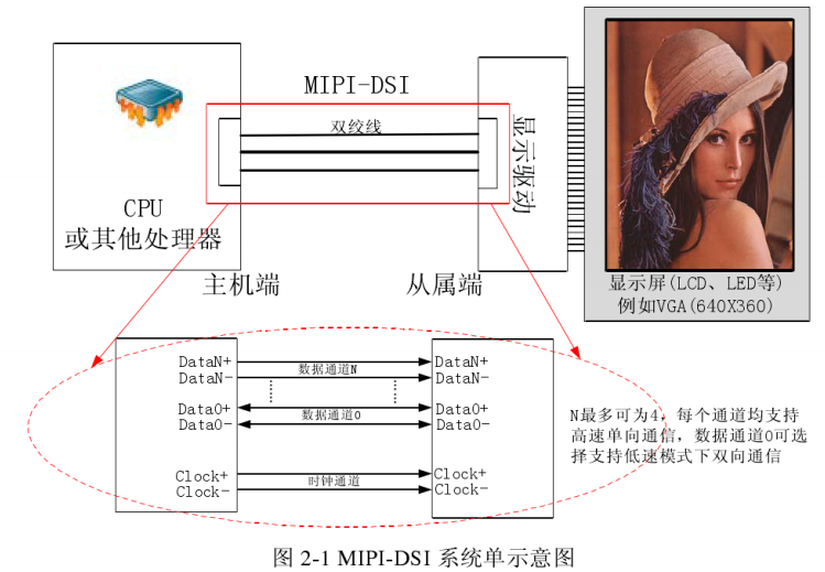
D- PHY的物理層支持HS(High Speed)和LP(Low Power)兩種工作模式
  • HS模式:低壓查分信號功耗大高速率(80M -1Gbps) 信號幅值(100mv-300mv)
  • LP模式:單端信號功耗小,速率低(< 10Mbps) 信號幅值(0-1.2V)
在高速模式下,通道狀態是差分的0或1,定義P比N高時定義為1,P比N低時定義為0,此時線上典型電壓為差分200mv
在LP模式下,只用lane0傳輸數據和時鐘,雙向數據傳輸。
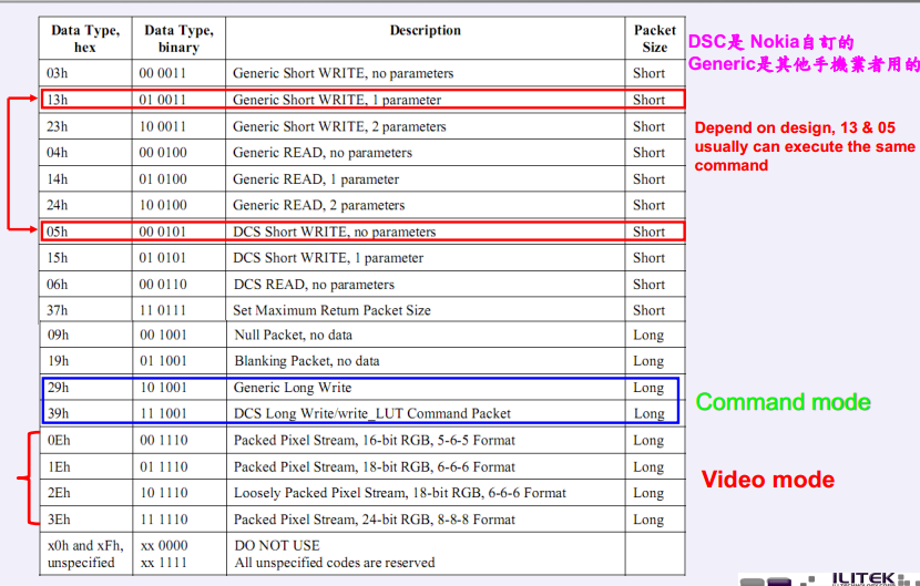
鏈路層的模式分為:Command模式Video模式
  • 鏈路層選擇Command模式時,物理層可以為HS模式,也可以為LP模式;
  • 鏈路層選擇Video模式時,物理層只能選擇HS模式。

Video模式時,物理層只能選擇HS模式,下面是video模式下傳遞一個些圖片像素數據包(長包)。
和command模式不同的是Data Type,這裡的Data Type是3Eh,下面有一張Data Type的表。


下面介紹一下qualcomm平台dtsi配置文件中關於對video模式配置說明:
qcom,mdss-dsi-panel-type =“ dsi_video_mode ”;
qcom,mdss-dsi-on-command = [29 01 00 00 00 00 04 B9 FF 83 94
29 01 00 00 00 00 02 C6 EF
05 01 00 00 78 00 02 11 00
05 01 00 00 14 00 02 29 00];
qcom,mdss-dsi-off-command = [05 01 00 00 32 00 02 28 00
05 01 00 00 78 00 02 10 00];
qcom,mdss-dsi-on-command-state =“dsi_lp_mode”;
qcom,mdss-dsi-off-command-state =“dsi_hs_mode”;
qcom,mdss-dsi-on-command是在Mdss_dsi_panel.c (drivers\video\msm\mdss)的
static int mdss_dsi_panel_on(struct mdss_panel_data *pdata)函數里用到的,點亮LCM的指令,未來這個函數將會被FB驅動resume裡面調用到。
類似的,qcom,mdss-dsi-off-command 同樣在文件
Mdss_dsi_panel.c (drivers\video\msm\mdss)的static int mdss_dsi_panel_off(struct mdss_panel_data *pdata)用到,未來將會被FB驅動的suspend函數里調用,用於關掉LCM的指令。

定義這個panel為" dsi_video_mode ",在下發mdss-dsi-on-command之後會把DSI轉換到video-hs模式下。

那麼mdss-dsi-on-command和mdss-dsi-off-command是什麼時候調用的呢?
如果按照MTK平台對LCM處理的思維,大概是這樣的:
LCM_DRIVER nt52021_hd720_dsi_vdo_lcm_drv =
{
.name =“nt52021_hd720_dsi_vdo”,
.set_util_funcs = lcm_set_util_funcs,
.get_params = lcm_get_params,
.init = lcm_init,//reset 調用DSI發初始化數據
.suspend = lcm_suspend,//調用DSI發滅panel數據
.resume = lcm_resume,//reset 調用DSI發初始化數據
.compare_id = lcm_compare_id,
#if(LCM_DSI_CMD_MODE)
.update = lcm_update,
#ENDIF
};
而高通平台是則是在LCM的FB驅動裡面,probe通過調用MDP驅動結構體的初始化函數,調用DSI驅動想MDPcore註冊的回調函數,這些回調函數就是操作DSI發送不同的數據,而這些數據恰恰就是dtsi裡面需要配置的mdss-dsi-on-command和mdss-dsi-off-command。

言歸正傳,前面說明了DSI 在video模式下面發送一些像素圖片的數據包內容,但是在實際傳輸這些數據包的時候需要遵守一些時序控制。
Video模式又分三種子模式:
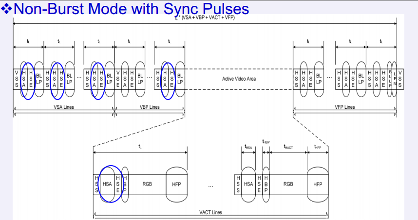
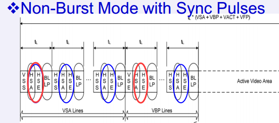
1 Non-burst Mode Sync pulses:在這種模式下,DSI基於各種不同的同步數據包來做數據同步。這種數據包括:重構,時間校準等。更具體的請參考DSI協議標準。
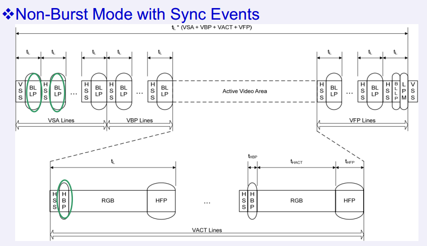
2 Non-burst Mode Sync event :這種模式和第一種模式很像,但是這種模式不會發重構和時間校準的數據包,它們只發送一種叫做”Sync event”的包。
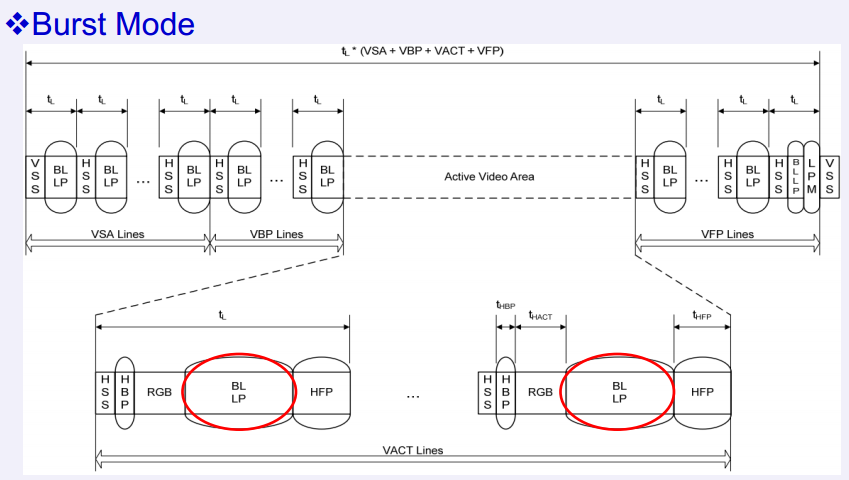
3 Burst mode:在horizo​​ntal的時序是一樣的情況下DSI會把連接的速度提升到Panel支持的最大速度。在這種模式下發送RGB數據包的時間被壓縮,以留出更多的時間用來傳送其他的數據。
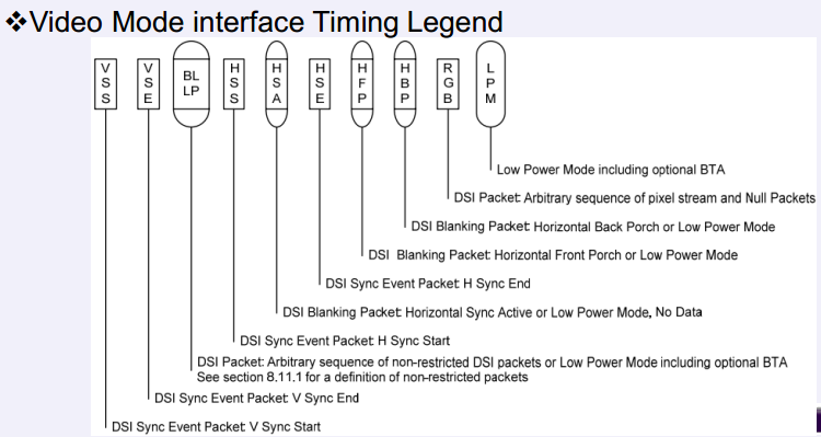
為了使能Video模式Host需要發送各種不同的包到panel用來設置開始和結束的Porch.以下是Video模式中用到的數據包:
•VSS:DSI同步事件包:V同步啟動
•VSE:DSI同步事件包:V同步結束
•BLLP:DSI數據包:任意序列的非限制性DSI數據包或低功耗模式,包括可選的BTA。
•HSS:DSI同步事件包:H同步開始
•HAS:DSI消隱數據包:水平同步活動或低功耗模式,無數據
•HSE:DSI同步事件包:H同步結束
•HFP:DSI消隱數據包:水平前沿或低功耗模式
•HBP:DSI消隱數據包:水平後沿或低功耗模式
•RGB:DSI包:像素流和空包的任意序列
•LPM:低功耗模式包含可選的BTA

上圖頂部有圓弧的代表數據包,長方形的代表時序的狀態。
那麼MIPI host如何輸入一幀的數據呢,下面分別是三種video mode下的數據傳輸時序圖:


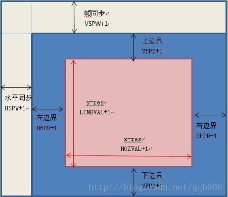
結合屏的物理結構才看得動上面時序圖的含義:


以BURST mode為例:
首先會發送VSPW行(VSA lines)的空數據包,在發送VBP lines的空數據包,接著發送VACT lines(屏寬)的有效RGB數據,其中每一行數據都包含HSS 行開始信號+HBP數據包+RGB+HFP數據包。最後就是發送VFP lines的空數據包。這樣就刷滿了一整屏,也就是一幀的數據。

那麼這三種video模式的區別就是傳遞的數序和數據包位置的不同,至於最終在dtsi配置哪一個模式就要根據實際的panel IC所支持video 模式來。
dtsi對應項:
qcom,mdss-dsi-traffic-mode =“non_burst_sync_event”;

另外說明一下dtsi 裡面qcom,mdss-dsi-h-sync-pulse 的含義
在kernel/Documentation/devicetree/bindings/fb/mdss-dsi-panel.txt:196中說明了:

這裡所說的pulse mode就是Non-burst Mode Sync pulses模式。
根據時序圖,如果這個值為1就會發圖中紅色圈圈的部分,如果為0就不會發,不過這個只用於這種模式下有效。