Source https://www.raspberrypi.org/documentation/configuration/device-tree.md
DEVICE TREES, OVERLAYS, AND PARAMETERS
Raspberry Pi's latest kernels and firmware, including Raspbian and NOOBS releases, now use a Device Tree (DT) to manage some resource allocation and module loading by default. This was implemented to alleviate the problem of multiple drivers contending for system resources, and to allow HAT modules to be auto-configured.
The current implementation is not a pure Device Tree system – there is still board support code that creates some platform devices – but the external interfaces (I2C, I2S, SPI), and the audio devices that use them, must now be instantiated using a Device Tree Blob (DTB) passed to the kernel by the loader (start.elf).
The main impact of using Device Tree is to change from
everything on, relying on module blacklisting to manage contention, to
everything off unless requested by the DTB. In order to continue to use external interfaces and the peripherals that attach to them, you will need to add some new settings to your
config.txt. Full details are given in
Part 3, but these are a few examples:
# Uncomment some or all of these lines to enable the optional hardware interfaces
#dtparam=i2c_arm=on
#dtparam=i2s=on
#dtparam=spi=on

# Uncomment one of these lines to enable an audio interface
#dtoverlay=hifiberry-amp
#dtoverlay=hifiberry-dac
#dtoverlay=hifiberry-dacplus
#dtoverlay=hifiberry-digi
#dtoverlay=iqaudio-dac
#dtoverlay=iqaudio-dacplus
#dtoverlay=audioinjector-wm8731-audio

# Uncomment this to enable the lirc-rpi module
#dtoverlay=lirc-rpi

# Uncomment this to override the defaults for the lirc-rpi module
#dtparam=gpio_out_pin=16
#dtparam=gpio_in_pin=17
#dtparam=gpio_in_pull=down
Device Trees
A Device Tree (DT) is a description of the hardware in a system. It should include the name of the base CPU, its memory configuration, and any peripherals (internal and external). A DT should not be used to describe the software, although by listing the hardware modules it does usually cause driver modules to be loaded. It helps to remember that DTs are supposed to be OS-neutral, so anything which is Linux-specific probably shouldn't be there.
A Device Tree represents the hardware configuration as a hierarchy of nodes. Each node may contain properties and subnodes. Properties are named arrays of bytes, which may contain strings, numbers (big-endian), arbitrary sequences of bytes, and any combination thereof. By analogy to a filesystem, nodes are directories and properties are files. The locations of nodes and properties within the tree can be described using a path, with slashes as separators and a single slash (/) to indicate the root.
1.1: BASIC DTS SYNTAX
Device Trees are usually written in a textual form known as Device Tree Source (DTS) and stored in files with a .dts suffix. DTS syntax is C-like, with braces for grouping and semicolons at the end of each line. Note that DTS requires semicolons after closing braces: think of C structs rather than functions. The compiled binary format is referred to as Flattened Device Tree (FDT) or Device Tree Blob (DTB), and is stored in .dtb files.
The following is a simple tree in the .dts format:
/dts-v1/;
/include/ "common.dtsi";

/ {
    node1 {
        a-string-property = "A string";
        a-string-list-property = "first string", "second string";
        a-byte-data-property = [0x01 0x23 0x34 0x56];
        cousin: child-node1 {
            first-child-property;
            second-child-property = <1>;
            a-string-property = "Hello, world";
        };
        child-node2 {
        };
    };
    node2 {
        an-empty-property;
        a-cell-property = <1 2="" 3="" 4="">; /* each number (cell) is a uint32 */
        child-node1 {
            my-cousin = <&cousin>;
        };
    };
};

/node2 {
    another-property-for-node2;
};
This tree contains:
- a required header:
/dts-v1/.
- The inclusion of another DTS file, conventionally named
*.dtsi and analogous to a .h header file in C - see An aside about /include/ below.
- a single root node:
/
- a couple of child nodes:
node1 and node2
- some children for node1:
child-node1 and child-node2
- a label (
cousin) and a reference to that label (&cousin): see Labels and References below.
- several properties scattered through the tree
- a repeated node (
/node2) - see An aside about /include/ below.
Properties are simple key-value pairs where the value can either be empty or contain an arbitrary byte stream. While data types are not encoded in the data structure, there are a few fundamental data representations that can be expressed in a Device Tree source file.
Text strings (NUL-terminated) are indicated with double quotes:
string-property = "a string";
Cells are 32-bit unsigned integers delimited by angle brackets:
cell-property = <0xbeef 0xabcd1234="" 123="">;
Arbitrary byte data is delimited with square brackets, and entered in hex:
binary-property = [01 23 45 67 89 ab cd ef];
Data of differing representations can be concatenated using a comma:
mixed-property = "a string", [01 23 45 67], <0x12345678>;
Commas are also used to create lists of strings:
string-list = "red fish", "blue fish";
1.2: AN ASIDE ABOUT /INCLUDE/
The /include/ directive results in simple textual inclusion, much like C's #include directive, but a feature of the Device Tree compiler leads to different usage patterns. Given that nodes are named, potentially with absolute paths, it is possible for the same node to appear twice in a DTS file (and its inclusions). When this happens, the nodes and properties are combined, interleaving and overwriting properties as required (later values override earlier ones).
In the example above, the second appearance of /node2 causes a new property to be added to the original:
/node2 {
    an-empty-property;
    a-cell-property = <1 2="" 3="" 4="">; /* each number (cell) is a uint32 */
    another-property-for-node2;
    child-node1 {
        my-cousin = <&cousin>;
    };
};
It is thus possible for one .dtsi to overwrite, or provide defaults for, multiple places in a tree.
1.3: LABELS AND REFERENCES
It is often necessary for one part of the tree to refer to another, and there are four ways to do this:
Path strings
Paths should be self-explanatory, by analogy with a filesystem - /soc/i2s@7e203000 is the full path to the I2S device in BCM2835 and BCM2836. Note that although it is easy to construct a path to a property (for example, /soc/i2s@7e203000/status), the standard APIs don't do that; you first find a node, then choose properties of that node.
phandles
A phandle is a unique 32-bit integer assigned to a node in its phandleproperty. For historical reasons, you may also see a redundant, matching linux,phandle. phandles are numbered sequentially, starting from 1; 0 is not a valid phandle. They are usually allocated by the DT compiler when it encounters a reference to a node in an integer context, usually in the form of a label (see below). References to nodes using phandles are simply encoded as the corresponding integer (cell) values; there is no markup to indicate that they should be interpreted as phandles, as that is application-defined.
Labels
Just as a label in C gives a name to a place in the code, a DT label assigns a name to a node in the hierarchy. The compiler takes references to labels and converts them into paths when used in string context (&node) and phandles in integer context (<&node>); the original labels do not appear in the compiled output. Note that labels contain no structure; they are just tokens in a flat, global namespace.
Aliases
Aliases are similar to labels, except that they do appear in the FDT output as a form of index. They are stored as properties of the /aliases node, with each property mapping an alias name to a path string. Although the aliases node appears in the source, the path strings usually appear as references to labels (&node), rather then being written out in full. DT APIs that resolve a path string to a node typically look at the first character of the path, treating paths that do not start with a slash as aliases that must first be converted to a path using the /aliases table.
1.4: DEVICE TREE SEMANTICS
How to construct a Device Tree, and how best to use it to capture the configuration of some hardware, is a large and complex subject. There are many resources available, some of which are listed below, but several points deserve mentioning in this document:
compatible properties are the link between the hardware description and the driver software. When an OS encounters a node with a compatible property, it looks it up in its database of device drivers to find the best match. In Linux, this usually results in the driver module being automatically loaded, provided it has been appropriately labelled and not blacklisted.
The status property indicates whether a device is enabled or disabled. If the status is ok, okay or absent, then the device is enabled. Otherwise, status should be disabled, so that the device is disabled. It can be useful to place devices in a .dtsi file with the status set to disabled. A derived configuration can then include that .dtsi and set the status for the devices which are needed to okay.
Part 2: Device Tree overlays
A modern SoC (System on a Chip) is a very complicated device; a complete Device Tree could be hundreds of lines long. Taking that one step further and placing the SoC on a board with other components only makes matters worse. To keep that manageable, particularly if there are related devices that share components, it makes sense to put the common elements in .dtsi files, to be included from possibly multiple .dts files.
But when a system like Raspberry Pi supports optional plug-in accessories, such as HATs, the problem grows. Ultimately, each possible configuration requires a Device Tree to describe it, but once you factor in different base hardware (models A, B, A+, and B+) and gadgets only requiring the use of a few GPIO pins that can coexist, the number of combinations starts to multiply rapidly.
What is needed is a way to describe these optional components using a partial Device Tree, and then to be able to build a complete tree by taking a base DT and adding a number of optional elements. You can do this, and these optional elements are called "overlays".
2.1: FRAGMENTS
A DT overlay comprises a number of fragments, each of which targets one node and its subnodes. Although the concept sounds simple enough, the syntax seems rather strange at first:
// Enable the i2s interface
/dts-v1/;
/plugin/;

/ {
    compatible = "brcm,bcm2708";

    fragment@0 {
        target = <&i2s>;
        __overlay__ {
            status = "okay";
        };
    };
};
The compatible string identifies this as being for BCM2708, which is the base architecture of the BCM2835 part. For the BCM2836 part you could use a compatible string of "brcm,bcm2709", but unless you are targeting features of the ARM CPUs, the two architectures should be equivalent, so sticking to "brcm,bcm2708" is reasonable. Then comes the first (and in this case only) fragment. Fragments are numbered sequentially from zero. Failure to adhere to this may cause some or all of your fragments to be missed.
Each fragment consists of two parts: a target property, identifying the node to apply the overlay to; and the __overlay__ itself, the body of which is added to the target node. The example above can be interpreted as if it were written like this:
/dts-v1/;

/ {
    compatible = "brcm,bcm2708";
};

&i2s {
    status = "okay";
};
The effect of merging that overlay with a standard Raspberry Pi base Device Tree (e.g. bcm2708-rpi-b-plus.dtb), provided the overlay is loaded afterwards, would be to enable the I2S interface by changing its status to okay. But if you try to compile this overlay using:
dtc -I dts -O dtb -o 2nd.dtbo 2nd-overlay.dts
you will get an error:
Label or path i2s not found
This shouldn't be too unexpected, since there is no reference to the base .dtb or .dts file to allow the compiler to find the i2s label.
Trying again, this time using the original example and adding the -@ option to allow unresolved references:
dtc -@ -I dts -O dtb -o 1st.dtbo 1st-overlay.dts
If dtc returns an error about the third line, it doesn't have the extensions required for overlay work. Run sudo apt-get install device-tree-compiler and try again - this time, compilation should complete successfully. Note that a suitable compiler is also available in the kernel tree as scripts/dtc/dtc, built when the dtbs make target is used:
make ARCH=arm dtbs
It is interesting to dump the contents of the DTB file to see what the compiler has generated:
$ fdtdump 1st.dtbo

/dts-v1/;
// magic:           0xd00dfeed
// totalsize:       0x106 (262)
// off_dt_struct:   0x38
// off_dt_strings:  0xe8
// off_mem_rsvmap:  0x28
// version:         17
// last_comp_version:    16
// boot_cpuid_phys: 0x0
// size_dt_strings: 0x1e
// size_dt_struct:  0xb0

/ {
    compatible = "brcm,bcm2708";
    fragment@0 {
        target = <0xdeadbeef>;
        __overlay__ {
            status = "okay";
        };
    };
    __fixups__ {
        i2s = "/fragment@0:target:0";
    };
};
After the verbose description of the file structure there is our fragment. But look carefully - where we wrote &i2s it now says 0xdeadbeef, a clue that something strange has happened. After the fragment there is a new node, __fixups__. This contains a list of properties mapping the names of unresolved symbols to lists of paths to cells within the fragments that need patching with the phandle of the target node, once that target has been located. In this case, the path is to the 0xdeadbeef value of target, but fragments can contain other unresolved references which would require additional fixes.
If you write more complicated fragments, the compiler may generate two more nodes: __local_fixups__ and __symbols__. The former is required if any node in the fragments has a phandle, because the program performing the merge will have to ensure that phandle numbers are sequential and unique. However, the latter is the key to how unresolved symbols are dealt with.
Back in section 1.3 it says that "the original labels do not appear in the compiled output", but this isn't true when using the -@ switch. Instead, every label results in a property in the __symbols__ node, mapping a label to a path, exactly like the aliases node. In fact, the mechanism is so similar that when resolving symbols, the Raspberry Pi loader will search the "aliases" node in the absence of a __symbols__ node. This is useful because by providing sufficient aliases, we can allow an older dtc to be used to build the base DTB files.
UPDATE: The
Dynamic Device Tree support in the kernel requires a different format of "local fixups" in the overlay. To avoid problems with old and new styles of overlay coexisting, and to match other users of overlays, the old "name-overlay.dtb" naming scheme has been replaced with "name.dtbo" from 4.4 onwards. Overlays should be referred to by name alone, and the firmware or utility that loads them will append the appropriate suffix. For example:
dtoverlay=awesome-overlay      # This is wrong
dtoverlay=awesome              # This is correct
2.2: DEVICE TREE PARAMETERS
To avoid the need for lots of Device Tree overlays, and to reduce the need for users of peripherals to modify DTS files, the Raspberry Pi loader supports a new feature - Device Tree parameters. This permits small changes to the DT using named parameters, similar to the way kernel modules receive parameters from modprobe and the kernel command line. Parameters can be exposed by the base DTBs and by overlays, including HAT overlays.
Parameters are defined in the DTS by adding an __overrides__ node to the root. It contains properties whose names are the chosen parameter names, and whose values are a sequence comprising a phandle (reference to a label) for the target node, and a string indicating the target property; string, integer (cell) and boolean properties are supported.
2.2.1: STRING PARAMETERS
String parameters are declared like this:
name = <&label>,"property";
where label and property are replaced by suitable values. String parameters can cause their target properties to grow, shrink, or be created.
Note that properties called status are treated specially; non-zero/true/yes/on values are converted to the string "okay", while zero/false/no/off becomes "disabled".
2.2.2: INTEGER PARAMETERS
Integer parameters are declared like this:
name = <&label>,"property.offset"; // 8-bit
name = <&label>,"property;offset"; // 16-bit
name = <&label>,"property:offset"; // 32-bit
name = <&label>,"property#offset"; // 64-bit
where label, property and offset are replaced by suitable values; the offset is specified in bytes relative to the start of the property (in decimal by default), and the preceding separator dictates the size of the parameter. In a change from earlier implementations, integer parameters may refer to non-existent properties or to offsets beyond the end of an existing property.
2.2.3: BOOLEAN PARAMETERS
Device Tree encodes boolean values as zero-length properties; if present then the property is true, otherwise it is false. They are defined like this:
boolean_property; // Set 'boolean_property' to true
Note that a property is assigned the value false by not defining it. Boolean parameters are declared like this:
name = <&label>,"property?";
where label and property are replaced by suitable values. Boolean parameters can cause properties to be created or deleted.
2.2.4 OVERLAY/FRAGMENT PARAMETERS
The DT parameter mechanism as described has a number of limitations, including the inability to change the name of a node and to write arbitrary values to arbitrary properties when a parameter is used. One way to overcome some of these limitations is to conditionally include or exclude certain fragments.
A fragment can be excluded from the final merge process (disabled) by renaming the __overlay__ node to __dormant__. The parameter declaration syntax has been extended to allow the otherwise illegal zero target phandle to indicate that the following string contains operations at fragment or overlay scope. So far, four operations have been implemented:
+    // Enable fragment
-    // Disable fragment
=    // Enable fragment  if the assigned parameter value is true, otherwise disable it
!    // Enable fragment  if the assigned parameter value is false, otherwise disable it
Examples:
just_one    = <0>,"+1-2"; // Enable 1, disable 2
conditional = <0>,"=3!4"; // Enable 3, disable 4 if value is true,
                          // otherwise disable 3, enable 4.
The i2c-mux overlay uses this technique.
2.2.5 EXAMPLES
Here are some examples of different types of properties, with parameters to modify them:
/ {
    fragment@0 {
        target-path = "/";
        __overlay__ {

            test: test_node {
                string = "hello";
                status = "disabled";
                bytes = /bits/ 8 <0x67 0x89="">;
                u16s = /bits/ 16 <0xabcd 0xef01="">;
                u32s = /bits/ 32 <0xfedcba98 0x76543210="">;
                u64s = /bits/ 64 < 0xaaaaa5a55a5a5555 0x0000111122223333>;
                bool1; // Defaults to true
                       // bool2 defaults to false
            };
        };
    };

    fragment@1 {
        target-path = "/";
        __overlay__ {
            frag1;
        };
    };

    fragment@2 {
        target-path = "/";
        __dormant__ {
            frag2;
        };
    };

    __overrides__ {
        string =      <&test>,"string";
        enable =      <&test>,"status";
        byte_0 =      <&test>,"bytes.0";
        byte_1 =      <&test>,"bytes.1";
        u16_0 =       <&test>,"u16s;0";
        u16_1 =       <&test>,"u16s;2";
        u32_0 =       <&test>,"u32s:0";
        u32_1 =       <&test>,"u32s:4";
        u64_0 =       <&test>,"u64s#0";
        u64_1 =       <&test>,"u64s#8";
        bool1 =       <&test>,"bool1?";
        bool2 =       <&test>,"bool2?";
        only1 =       <0>,"+1-2";
        only2 =       <0>,"-1+2";
        toggle1 =     <0>,"=1";
        toggle2 =     <0>,"=2";
        not1 =        <0>,"!1";
        not2 =        <0>,"!2";
    };
};
2.2.6: PARAMETERS WITH MULTIPLE TARGETS
There are some situations where it is convenient to be able to set the same value in multiple locations within the Device Tree. Rather than the ungainly approach of creating multiple parameters, it is possible to add multiple targets to a single parameter by concatenating them, like this:
    __overrides__ {
        gpiopin = <&w1>,"gpios:4",
                  <&w1_pins>,"brcm,pins:0";
        ...
    };
(example taken from the w1-gpio overlay)
Note that it is even possible to target properties of different types with a single parameter. You could reasonably connect an "enable" parameter to a statusstring, cells containing zero or one, and a proper boolean property.
2.2.7: FURTHER OVERLAY EXAMPLES
There is a growing collection of overlay source files hosted in the Raspberry Pi/Linux GitHub repository
here.
Part 3: Using Device Trees on Raspberry Pi
3.1: OVERLAYS AND CONFIG.TXT
On a Raspberry Pi it is the job of the loader (one of the start.elf images) to combine overlays with an appropriate base device tree, and then to pass a fully resolved Device Tree to the kernel. The base Device Trees are located alongside start.elf in the FAT partition (/boot from Linux), named bcm2708-rpi-b.dtb, bcm2708-rpi-b-plus.dtb, bcm2708-rpi-cm.dtb, and bcm2709-rpi-2-b.dtb. Note that Models A and A+ will use the "b" and "b-plus" variants, respectively. This selection is automatic, and allows the same SD card image to be used in a variety of devices.
Note that DT and ATAGs are mutually exclusive. As a result, passing a DT blob to a kernel that doesn't understand it causes a boot failure. To guard against this, the loader checks kernel images for DT-compatibility, which is marked by a trailer added by the mkknlimg utility; this can be found in the scripts directory of a recent kernel source tree. Any kernel without a trailer is assumed to be non-DT-capable.
A kernel built from the rpi-4.4.y tree (and later) will not function without a DTB, so from the 4.4 releases onwards, any kernel without a trailer is assumed to be DT-capable. You can override this by adding a trailer without the DTOK flag or by putting device_tree= in config.txt, but don't be surprised if it doesn't work. N.B. A corollary to this is that if the kernel has a trailer indicating DT capability then device_tree= will be ignored.
The loader now supports builds using bcm2835_defconfig, which selects the upstreamed BCM2835 support. This configuration will cause bcm2835-rpi-b.dtb and bcm2835-rpi-b-plus.dtb to be built. If these files are copied with the kernel, and if the kernel has been tagged by a recent mkknlimg, then the loader will attempt to load one of those DTBs by default.
In order to manage Device Tree and overlays, the loader supports a number of new config.txt directives:
dtoverlay=acme-board
dtparam=foo=bar,level=42
This will cause the loader to look for overlays/acme-board.dtbo in the firmware partition, which Raspbian mounts on /boot. It will then search for parameters foo and level, and assign the indicated values to them.
The loader will also search for an attached HAT with a programmed EEPROM, and load the supporting overlay from there; this happens without any user intervention.
There are several ways to tell that the kernel is using Device Tree:
- The "Machine model:" kernel message during bootup has a board-specific value such as "Raspberry Pi 2 Model B", rather than "BCM2709".
- Some time later, there may also be another kernel message saying "No ATAGs?" - this is expected.
/proc/device-tree exists, and contains subdirectories and files that exactly mirror the nodes and properties of the DT.
With a Device Tree, the kernel will automatically search for and load modules that support the indicated enabled devices. As a result, by creating an appropriate DT overlay for a device you save users of the device from having to edit /etc/modules; all of the configuration goes in config.txt, and in the case of a HAT, even that step is unnecessary. Note, however, that layered modules such as i2c-dev still need to be loaded explicitly.
The flipside is that because platform devices don't get created unless requested by the DTB, it should no longer be necessary to blacklist modules that used to be loaded as a result of platform devices defined in the board support code. In fact, current Raspbian images ship without a blacklist file.
3.2: DT PARAMETERS
As described above, DT parameters are a convenient way to make small changes to a device's configuration. The current base DTBs support parameters for enabling and controlling the onboard audio, I2C, I2S and SPI interfaces without using dedicated overlays. In use, parameters look like this:
dtparam=audio=on,i2c_arm=on,i2c_arm_baudrate=400000,spi=on
Note that multiple assignments can be placed on the same line, but ensure you don't exceed the 80-character limit.
A future default config.txt may contain a section like this:
# Uncomment some or all of these to enable the optional hardware interfaces
#dtparam=i2c_arm=on
#dtparam=i2s=on
#dtparam=spi=on
If you have an overlay that defines some parameters, they can be specified either on subsequent lines like this:
dtoverlay=lirc-rpi
dtparam=gpio_out_pin=16
dtparam=gpio_in_pin=17
dtparam=gpio_in_pull=down
or appended to the overlay line like this:
dtoverlay=lirc-rpi:gpio_out_pin=16,gpio_in_pin=17,gpio_in_pull=down
Note here the use of a colon (:) to separate the overlay name from its parameters, which is a supported syntax variant.
Overlay parameters are only in scope until the next overlay is loaded. In the event of a parameter with the same name being exported by both the overlay and the base, the parameter in the overlay takes precedence; for clarity, it's recommended that you avoid doing this. To expose the parameter exported by the base DTB instead, end the current overlay scope using:
dtoverlay=
3.3: BOARD-SPECIFIC LABELS AND PARAMETERS
Raspberry Pi boards have two I2C interfaces. These are nominally split: one for the ARM, and one for VideoCore (the "GPU"). On almost all models, i2c1 belongs to the ARM and i2c0 to VC, where it is used to control the camera and read the HAT EEPROM. However, there are two early revisions of the Model B that have those roles reversed.
To make it possible to use one set of overlays and parameters with all Pis, the firmware creates some board-specific DT parameters. These are:
i2c/i2c_arm
i2c_vc
i2c_baudrate/i2c_arm_baudrate
i2c_vc_baudrate
These are aliases for i2c0, i2c1, i2c0_baudrate, and i2c1_baudrate. It is recommended that you only use i2c_vc and i2c_vc_baudrate if you really need to - for example, if you are programming a HAT EEPROM. Enabling i2c_vccan stop the Pi Camera being detected.
For people writing overlays, the same aliasing has been applied to the labels on the I2C DT nodes. Thus, you should write:
fragment@0 {
    target = <&i2c_arm>;
    __overlay__ {
        status = "okay";
    };
};
Any overlays using the numeric variants will be modified to use the new aliases.
3.4: HATS AND DEVICE TREE
A Raspberry Pi HAT is an add-on board for a "Plus"-shaped (A+, B+ or Pi 2 B) Raspberry Pi with an embedded EEPROM. The EEPROM includes any DT overlay required to enable the board, and this overlay can also expose parameters.
The HAT overlay is automatically loaded by the firmware after the base DTB, so its parameters are accessible until any other overlays are loaded, or until the overlay scope is ended using dtoverlay=. If for some reason you want to suppress the loading of the HAT overlay, put dtoverlay= before any other dtoverlay or dtparam directive.
3.5: DYNAMIC DEVICE TREE
As of Linux 4.4, the RPi kernels support the dynamic loading of overlays and parameters. Compatible kernels manage a stack of overlays that are applied on top of the base DTB. Changes are immediately reflected in /proc/device-tree and can cause modules to be loaded and platform devices to be created and destroyed.
The use of the word "stack" above is important - overlays can only be added and removed at the top of the stack; changing something further down the stack requires that anything on top of it must first be removed.
There are some new commands for managing overlays:
3.5.1 THE DTOVERLAY COMMAND
dtoverlay is a command line utility that loads and removes overlays while the system is running, as well as listing the available overlays and displaying their help information:
pi@raspberrypi ~ $ dtoverlay -h
Usage:
  dtoverlay  [=...]
                           Add an overlay (with parameters)
  dtoverlay -r [] Remove an overlay (by name, index or the last)
  dtoverlay -R [] Remove from an overlay (by name, index or all)
  dtoverlay -l             List active overlays/params
  dtoverlay -a             List all overlays (marking the active)
  dtoverlay -h             Show this usage message
  dtoverlay -h    Display help on an overlay
  dtoverlay -h  ..  Or its parameters
    where  is the name of an overlay or 'dtparam' for dtparams
Options applicable to most variants:
    -d     Specify an alternate location for the overlays
                (defaults to /boot/overlays or /flash/overlays)
    -n          Dry run - show what would be executed
    -v          Verbose operation
Unlike the
config.txt equivalent, all parameters to an overlay must be included in the same command line - the
dtparam command is only for parameters of the base DTB.
Two points to note:
Command variants that change kernel state (adding and removing things) require root privilege, so you may need to prefix the command with sudo.
- Only overlays and parameters applied at run-time can be unloaded - an overlay or parameter applied by the firmware becomes "baked in" such that it won't be listed by
dtoverlay and can't be removed.
3.5.2 THE DTPARAM COMMAND
dtparam creates an overlay that has the same effect as using a dtparam directive in config.txt. In usage it is largely equivalent to dtoverlay with an overlay name of -, but there are a few small differences:
dtparam will list the help information for all known parameters of the base DTB. Help on the dtparam command is still available using dtparam -h.
- When indicating a parameter for removal, only index numbers can be used (not names).
3.5.3 GUIDELINES FOR WRITING RUNTIME-CAPABLE OVERLAYS
This area is poorly documented, but here are some accumulated tips:
The creation or deletion of a device object is triggered by a node being added or removed, or by the status of a node changing from disabled to enabled or vice versa. Beware - the absence of a "status" property means the node is enabled.
Don't create a node within a fragment that will overwrite an existing node in the base DTB - the kernel will rename the new node to make it unique. If you want to change the properties of an existing node, create a fragment that targets it.
- ALSA doesn't prevent its codecs and other components from being unloaded while they are in use. Removing an overlay can cause a kernel exception if it deletes a codec that is still being used by a sound card. Experimentation found that devices are deleted in the reverse of fragment order in the overlay, so placing the node for the card after the nodes for the components allows an orderly shutdown.
3.5.4 CAVEATS
The loading of overlays at runtime is a recent addition to the kernel, and so far there is no accepted way to do this from userspace. By hiding the details of this mechanism behind commands the aim is to insulate users from changes in the event that a different kernel interface becomes standardised.
Some overlays work better at run-time than others. Parts of the Device Tree are only used at boot time - changing them using an overlay will not have any effect.
Applying or removing some overlays may cause unexpected behaviour, so it should be done with caution. This is one of the reasons it requires sudo.
Unloading the overlay for an ALSA card can stall if something is actively using ALSA - the LXPanel volume slider plugin demonstrates this effect. To enable overlays for sound cards to be removed, the lxpanelctl utility has been given two new options - alsastop and alsastart - and these are called from the auxiliary scripts dtoverlay-pre and dtoverlay-post before and after overlays are loaded or unloaded, respectively.
Removing an overlay will not cause a loaded module to be unloaded, but it may cause the reference count of some modules to drop to zero. Running rmmod -a twice will cause unused modules to be unloaded.
Overlays have to be removed in reverse order. The commands will allow you to remove an earlier one, but all the intermediate ones will be removed and re-applied, which may have unintended consequences.
- Adding clocks under the
/clocks node at run-time doesn't cause a new clock provider to be registered, so devm_clk_get will fail for a clock created in an overlay.
3.6: SUPPORTED OVERLAYS AND PARAMETERS
As it is too time-consuming to document the individual overlays here, please refer to the
README file found alongside the overlay
.dtbo files in
/boot/overlays. It is kept up-to-date with additions and changes.
Part 4: Troubleshooting and pro tips
4.1: DEBUGGING
The loader will skip over missing overlays and bad parameters, but if there are serious errors, such as a missing or corrupt base DTB or a failed overlay merge, then the loader will fall back to a non-DT boot. If this happens, or if your settings don't behave as you expect, it is worth checking for warnings or errors from the loader:
sudo vcdbg log msg
Extra debugging can be enabled by adding dtdebug=1 to config.txt.
If the kernel fails to come up in DT mode, this is probably because the kernel image does not have a valid trailer. Use knlinfo to check for one, and the mkknlimg utility to add one. Both utilities are included in the scripts directory of current Raspberry Pi kernel source trees.
You can create a human-readable representation of the current state of DT like this:
dtc -I fs /proc/device-tree
This can be useful to see the effect of merging overlays onto the underlying tree.
If kernel modules don't load as expected, check that they aren't blacklisted in /etc/modprobe.d/raspi-blacklist.conf; blacklisting shouldn't be necessary when using Device Tree. If that shows nothing untoward, you can also check that the module is exporting the correct aliases by searching /lib/modules//modules.alias for the compatible value. Otherwise, your driver is probably missing either:
.of_match_table = xxx_of_match,
or:
MODULE_DEVICE_TABLE(of, xxx_of_match);
Failing that, depmod has failed or the updated modules haven't been installed on the target filesystem.
4.2: TESTING OVERLAYS USING DTMERGE AND DTDIFF
Alongside the dtoverlay and dtparam commands is a utility for applying an overlay to a DTB - dtmerge. To use it you first need to obtain your base DTB, which can be obtained in one of two ways:
a) generate it from the live DT state in /proc/device-tree:
dtc -I fs -O dtb -o base.dtb /proc/device-tree
This will include any overlays and parameters you have applied so far, either in config.txt or by loading them at runtime, which may or may not be what you want. Alternatively...
b) copy it from the source DTBs in /boot. This won't include overlays and parameters, but it also won't include any other modifications by the firmware. To allow testing of all overlays, the dtmerge utility will create some of the board-specific aliases ("i2c_arm", etc.), but this means that the result of a merge will include more differences from the original DTB than you might expect. The solution to this is to use dtmerge to make the copy:
dtmerge /boot/bcm2710-rpi-3-b.dtb base.dtb -
(the - indicates an absent overlay name).
You can now try applying an overlay or parameter:
dtmerge base.dtb merged.dtb - sd_overclock=62
dtdiff base.dtb merged.dtb
which will return:
--- /dev/fd/63  2016-05-16 14:48:26.396024813 +0100
+++ /dev/fd/62  2016-05-16 14:48:26.396024813 +0100
@@ -594,7 +594,7 @@
                };

                sdhost@7e202000 {
-                       brcm,overclock-50 = <0x0>;
+                       brcm,overclock-50 = <0x3e>;
                        brcm,pio-limit = <0x1>;
                        bus-width = <0x4>;
                        clocks = <0x8>;
You can also compare different overlays or parameters.
dtmerge base.dtb merged1.dtb /boot/overlays/spi1-1cs.dtbo
dtmerge base.dtb merged2.dtb /boot/overlays/spi1-2cs.dtbo
dtdiff merged1.dtb merged2.dtb
to get:
--- /dev/fd/63  2016-05-16 14:18:56.189634286 +0100
+++ /dev/fd/62  2016-05-16 14:18:56.189634286 +0100
@@ -453,7 +453,7 @@

                        spi1_cs_pins {
                                brcm,function = <0x1>;
-                               brcm,pins = <0x12>;
+                               brcm,pins = <0x12 0x11="">;
                                phandle = <0x3e>;
                        };

@@ -725,7 +725,7 @@
                        #size-cells = <0x0>;
                        clocks = <0x13 0x1="">;
                        compatible = "brcm,bcm2835-aux-spi";
-                       cs-gpios = <0xc 0x12="" 0x1="">;
+                       cs-gpios = <0xc 0x11="" 0x12="" 0x1="" 0xc="">;
                        interrupts = <0x1 0x1d="">;
                        linux,phandle = <0x30>;
                        phandle = <0x30>;
@@ -743,6 +743,16 @@
                                spi-max-frequency = <0x7a120>;
                                status = "okay";
                        };
+
+                       spidev@1 {
+                               #address-cells = <0x1>;
+                               #size-cells = <0x0>;
+                               compatible = "spidev";
+                               phandle = <0x41>;
+                               reg = <0x1>;
+                               spi-max-frequency = <0x7a120>;
+                               status = "okay";
+                       };
                };

                spi@7e2150C0 {
4.3: FORCING A SPECIFIC DEVICE TREE
If you have very specific needs that aren't supported by the default DTBs (in particular, people experimenting with the pure-DT approach used by the ARCH_BCM2835 project), or if you just want to experiment with writing your own DTs, you can tell the loader to load an alternate DTB file like this:
device_tree=my-pi.dtb
4.4: DISABLING DEVICE TREE USAGE
Since the switch to the 4.4 kernel and the use of more upstream drivers, Device Tree usage is required in Pi kernels. The method of disabling DT usage is to add:
device_tree=
to config.txt. However, if the kernel has a mkknlimg trailer indicating DT capability then this directive will be ignored.
4.5: SHORTCUTS AND SYNTAX VARIANTS
The loader understands a few shortcuts:
dtparam=i2c_arm=on
dtparam=i2s=on
can be shortened to:
dtparam=i2c,i2s
(i2c is an alias of i2c_arm, and the =on is assumed). It also still accepts the long-form versions: device_tree_overlay and device_tree_param.
The loader used to accept the use of whitespace and colons as separators, but support for these has been discontinued for simplicity and so they can be used within parameter values without quotes.
4.6: OTHER DT COMMANDS AVAILABLE IN CONFIG.TXT
device_tree_address This is used to override the address where the firmware loads the device tree (not dt-blob). By default the firmware will choose a suitable place.
device_tree_end This sets an (exclusive) limit to the loaded device tree. By default the device tree can grow to the end of usable memory, which is almost certainly what is required.
dtdebug If non-zero, turn on some extra logging for the firmware's device tree processing.
enable_uart Enable the primary/console UART (ttyS0 on a Pi 3, ttyAMA0 otherwise - unless swapped with an overlay such as pi3-miniuart-bt). If the primary UART is ttyAMA0 then enable_uart defaults to 1 (enabled), otherwise it defaults to 0 (disabled). This is because it is necessary to stop the core frequency from changing which would make ttyS0 unusable, so
enable_uart=1 implies core_freq=250 (unless force_turbo=1). In some cases this is a performance hit, so it is off by default. More details on UARTs can be found
here
overlay_prefix Specifies a subdirectory/prefix from which to load overlays - defaults to "overlays/". Note the trailing "/". If desired you can add something after the final "/" to add a prefix to each file, although this is not likely to be needed.
Further ports can be controlled by the DT, for more details see
section 3.
 數據在Flash內存單元中是以電荷(electrical charge) 形式存儲的。存儲電荷的多少,取決於圖中的外部門(external gate)所被施加的電壓,其控制了是向存儲單元中衝入電荷還是使其釋放電荷。而數據的表示,以所存儲的電荷的電壓是否超過一個特定的閾值Vth來表示,因此,Flash的存儲單元的默認值,不是0(其他常見的存儲設備,比如硬盤燈,默認值為0),而是1,而如果將電荷釋放掉,電壓降低到一定程度,表述數字0。
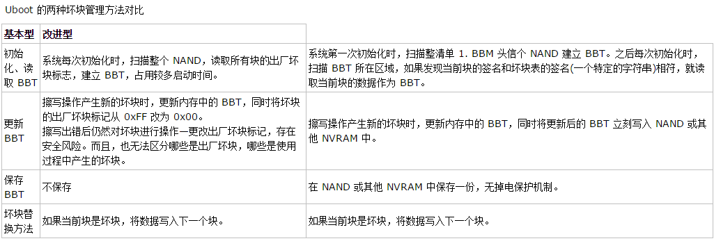 雖然 uboot 的改進型壞塊管理方法的做了一些改進,但它仍然有三個主要的缺點。
 為了實現共用好塊池,需要創建一個從壞塊到好塊的映射,所以,除了 BBT 之外,還需定義一個替換表(SBT)。這樣一來,當讀第 i 個塊的數據時,如果發現 BBT 中記錄該塊為壞塊,就去 SBT 中查詢其替換塊;如果寫第 i 個塊出錯,需要在 BBT 中標記該塊為壞塊,同時從好塊池中獲取一個新的好塊,假設其序號為 j,然後將此好塊的序號 j 寫入 SBT 中的第 i 個字節,而且 SBT 的第 j 個字節寫序號 i。SBT 中的這種雙向映射可確保數據的可靠性。此外,好塊池中的塊也有可能成為壞塊,如果掃描時發現是壞塊,則將 SBT 中的對應位置標記為 0x00,如果是在寫的過程中出錯,則除了在 SBT 對應位置標記 0x00 之外,還要更新雙向映射數據。
BBT/SBT 映射示意圖
為了實現共用好塊池,需要創建一個從壞塊到好塊的映射,所以,除了 BBT 之外,還需定義一個替換表(SBT)。這樣一來,當讀第 i 個塊的數據時,如果發現 BBT 中記錄該塊為壞塊,就去 SBT 中查詢其替換塊;如果寫第 i 個塊出錯,需要在 BBT 中標記該塊為壞塊,同時從好塊池中獲取一個新的好塊,假設其序號為 j,然後將此好塊的序號 j 寫入 SBT 中的第 i 個字節,而且 SBT 的第 j 個字節寫序號 i。SBT 中的這種雙向映射可確保數據的可靠性。此外,好塊池中的塊也有可能成為壞塊,如果掃描時發現是壞塊,則將 SBT 中的對應位置標記為 0x00,如果是在寫的過程中出錯,則除了在 SBT 對應位置標記 0x00 之外,還要更新雙向映射數據。
BBT/SBT 映射示意圖

 使用三重 CRC 校驗機制,無論 BBT 保存在哪種存儲體中,都可以更加嚴格地驗證數據的有效性。
