2018年11月22日 星期四

TODO: 3GPP

Source http://www.sharetechnote.com/html/Handbook_LTE_PUCCH_Format.html

LTE Quick Reference                                  Go Back To Index    Home : www.sharetechnote.com 


PUCCH (Physical Uplink Control Channel) carries a set of information called "UCI(Uplink Control Information)". (This is similar to PDCCH which carries DCI (Downlink control information)". Depending on what kind of information the UCI in PUCCH carries, PUCCH is classified into various formation as follows.
You may see a lot of different way of describing these formats depending on situation. It may be confusing at the beginning, but it would be better for you to get familiar with those different way of expression. You may want a single big table which has every details, but you will notice that those big table would be even more confusing.
So I will try to describe these formats in this page in various ways with a little bit different focus. You will see all of these are saying the same thing.. but in a little bit different perspective.

In 3GPP 36.213, section 10.1 UE procedure for determining physical uplink control channel assignment. The PUCCH format is summarized as follows.
  • HARQ-ACK using PUCCH format 1a or 1b
  • HARQ-ACK using PUCCH format 1b with channel selection
  • Scheduling request (SR) using PUCCH format 1
  • HARQ-ACK and SR using PUCCH format 1a or 1b
  • CQI using PUCCH format 2
  • CQI and HARQ-ACK using PUCCH format
  • 2a or 2b for normal cyclic prefix
  • 2 for extended cyclic prefix

Following is a tabular format of description of specification described above in 3GPP specification (36.213-10.1.1 PUCCH format information).
PUCCH Format
UCI information
Format 1Scheduling Request (SR)
Format 1a1-bit HARQ ACK/NACK with/without SR
Format 1b
FDD (1CC)
2-bit HARQ ACK/NACK with/without SR (This is for MIMO, 1 bit for each transport block)
FDD (2CC)
4-bit HARQ ACK/NACK with channel selection
TDD (1CC)
4-bit HARQ ACK/NACK
Format 2CQI (20 coded bits)
Format 2CQI and 1 or 2 bit HARQ ACK/NACK - 20 bits - Extended CP only
Format 2aCQI and 1  bit HARQ ACK/NACK - (20 + 1 coded bits)
Format 2bCQI and 2  bit HARQ ACK/NACK - (20 + 2 coded bits)
Format 3
FDD(up to 5CC)
up to 10 bit HARQ ACK
TDD(up to 5CC)
up to 20 bit HARQ ACK
Format 3
FDD(up to 5CC)
11 bit corresponding to 10 bit HARQ ACK and 1 bit positive/negative SR
TDD(up to 5CC)
21 bit corresponding to 20 bit HARQ ACK and 1 bit positive/negative SR
Format 3HARQ-ACK, 1-bit positive/negative SR (if any) and CSI report(s).
Format 4more than 22 bits of UCI including HARQ-ACK, SR (if any) and periodic CSI report(s) (if any).
Format 4more than one CSI report and SR (if any).
Format 5more than 22 bits of UCI including HARQ-ACK, SR (if any) and periodic CSI report(s) (if any).
Format 5more than one CSI report and SR (if any).

Following is another tabular format of description of specification, this is intended to give you idea on the contents of HARQ and CSI.
PUCCH Format
Number of Bits
UCI information
Format 1

No Ack/Nack, SR only
Format 1a
1
SISO Ack/Nack
Format 1b
FDD (1CC)
2
MIMO Ack/Nack
FDD (2CC)
4
MIMO Ack/Nack
TDD (1CC)
4
MIMO Ack/Nack
Format 2
20
CSI, no Ack/Nack
Format 2a
21
CSI + SISO Ack/Nack
Format 2b
22
CSI + MIMO Ack/Nack
Format 3
FDD(up to 5CC)
10
Ack/Nack (up to 5CC)
TDD(up to 5CC)
20
Ack/Nack (up to 5CC)
Format 3
FDD(up to 5CC)
11
Ack/Nack (up to 5CC) + SR
TDD(up to 5CC)
21
Ack/Nack (up to 5CC) + SR
NOTE : 'Number of Bits' here the bit length after PUCCH channel coding. In short, the number of ACK/NACK bits does not change by channel coding process, but the number of CSI (e.g, CQI) increases to 20 bits. See PUCCH Channel Coding page.


Important Questions about PUCCH

Overall logics about PUCCH was relatively simple at Rel 8, but as it gets evolved the rule gets complicated and a lot of confusions start arising. A couple of questions you have to keep asking yourself about PUCCHs are
  • At a certain subframe, does UE has to transmit PUCCH or PUSCH ?
  • If UE has to transmit PUCCH, what kind of PUCCH format it has to transmit ? what kind of information it should carry ?
Question is simple,but the answer would get different depending on situation. To figure out the correct answer to these questions, you need to have clear understanding not only on HARQ mechanism, but also on CSI mechanism. HARQ mechanism is relatively simple, but CSI mechanism is pretty complex.. and it gets extremely complicated as it evolves to Rel 9,10,11.


Physical Layer Configuraion for PUCCH

If you are mostly working on higher layer signaling (e.g, RRC or NAS) and has to configure PUCCH details in RRC message, you would have some difficulties of understanding/setting physical layer configuration of PUCCH. Following topics would help you in this aspect.


Source https://blog.csdn.net/m_052148/article/details/51982050

LTE上行物理层传输机制(1)-PUSCH上行跳频之Type1频率跳频

版权声明:本文为博主辛苦原创,转载时请注明原文链接(http://blog.csdn.net/m_052148),谢谢 https://blog.csdn.net/m_052148/article/details/51982050
1.什么是PUSCH频率跳频(PUSCH Frequency Hopping)
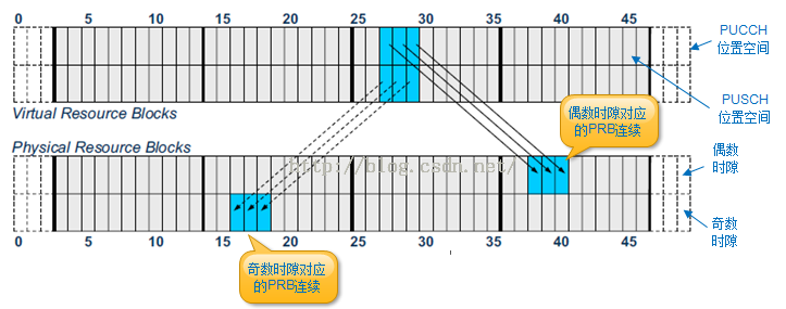
博文《LTE下行物理层传输机制(9)-集中式和分布式资源映射》中提到了分布式的下行资源分配,这种资源分配方式可以有效利用频率的分集效应,增加信号的抗干扰作用。实际上在上行传输过程中,也存在着类似的分布式资源分配,即连续的VRB对映射到不连续的PRB对中,这种方式就叫做PUSCH频率跳频(PUSCH Frequency Hopping)。由于上行分配的RB必须使用连续的子载波,因此eNB分配的VRB必须是连续的,并且同一个时隙内连续的VRB必须映射到连续的PRB,如下图所示。
2.为什么要采用PUSCH跳频
采用跳频是为了利用频率的分集效应,增加信号的抗干扰作用。不妨首先考虑下面图1这种RB分配方式。在图1中,eNB在每个子帧subframe的每个时隙slot都分配了若干个连续的RB,用于PUSCH的传输,这个时候看起来并没有问题。
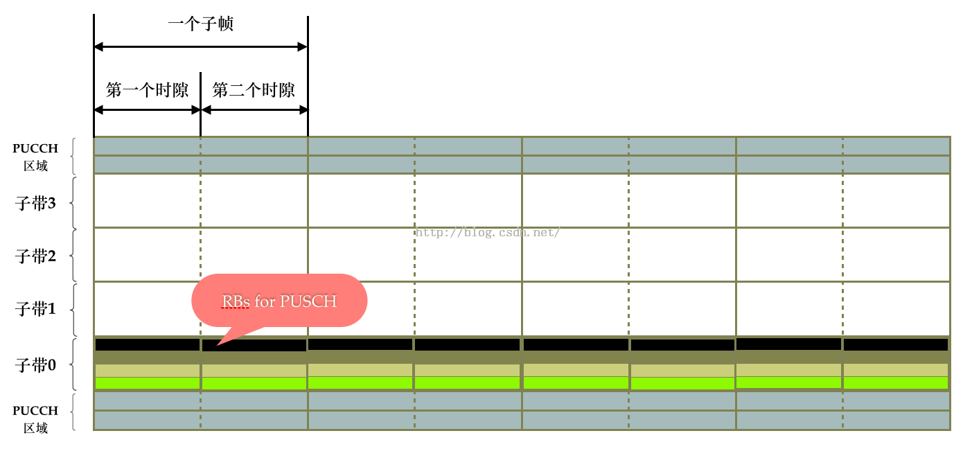
(图1)
然而在某个时刻,系统突然出现了较强的干扰,并且该干扰正好出现在已分配的RB附近,如图2所示。如果这个时候系统没有其他的抗干扰措施,势必会影响PUSCH数据的传输。
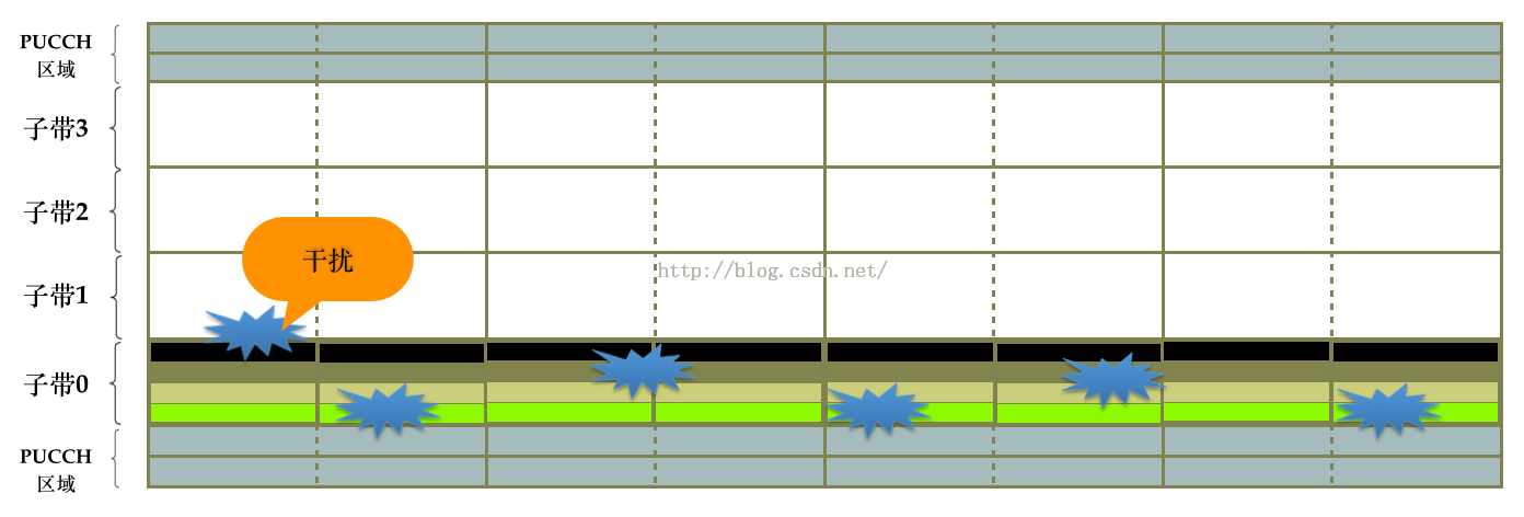
(图2)
在这种情况下,为了提高数据传输的可靠性,选择PUSCH跳频可以是其中的一种方案(当然我们在实际设计算法的时候,也会综合采用其他的一些调度策略,因为不涉及到协议规范内容,这里就不做说明)。我们可以采用图3所示的这种跳频方式,这种跳频模式叫做子帧间跳频inter-subframe hopping)。子帧间跳频的策略思想是在不同的子帧里分配的RB位置要错开,从而达到分布式的目的。
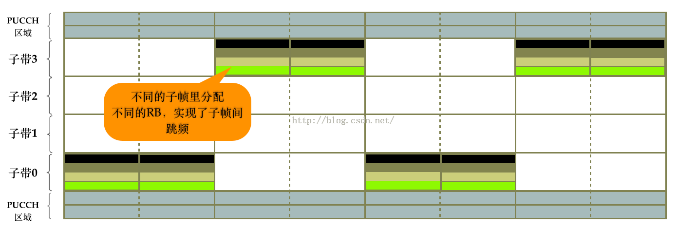
(图3 子帧间跳频)
图3所示的子帧间的跳频模式虽然达到了频率分集的效果,但是同一个子帧内的RB并没有分开,因此这种跳频方式并不彻底,还可以继续优化,所以出现了图4所示的这种跳频方式。图4的这种跳频模式叫做子帧内和子帧间跳频(IntraAndInter-subframe hopping)。
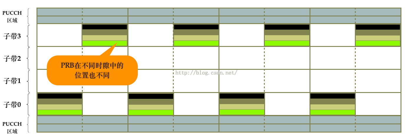
(图4 子帧内和子帧间跳频)
图4所示的跳频方式能明显看到存在着一定的规律性:不同子帧间的偶数时隙与偶数时隙、奇数时隙与奇数时隙,它们的PRB位置是相同的。因为实际环境中的干扰存在着诸多的不确定性,因此如果PRB的映射位置不那么规律一点,则频率分集效果会更好些,因此实际分配时会出现诸如图5所示的子帧内和子帧间跳频。
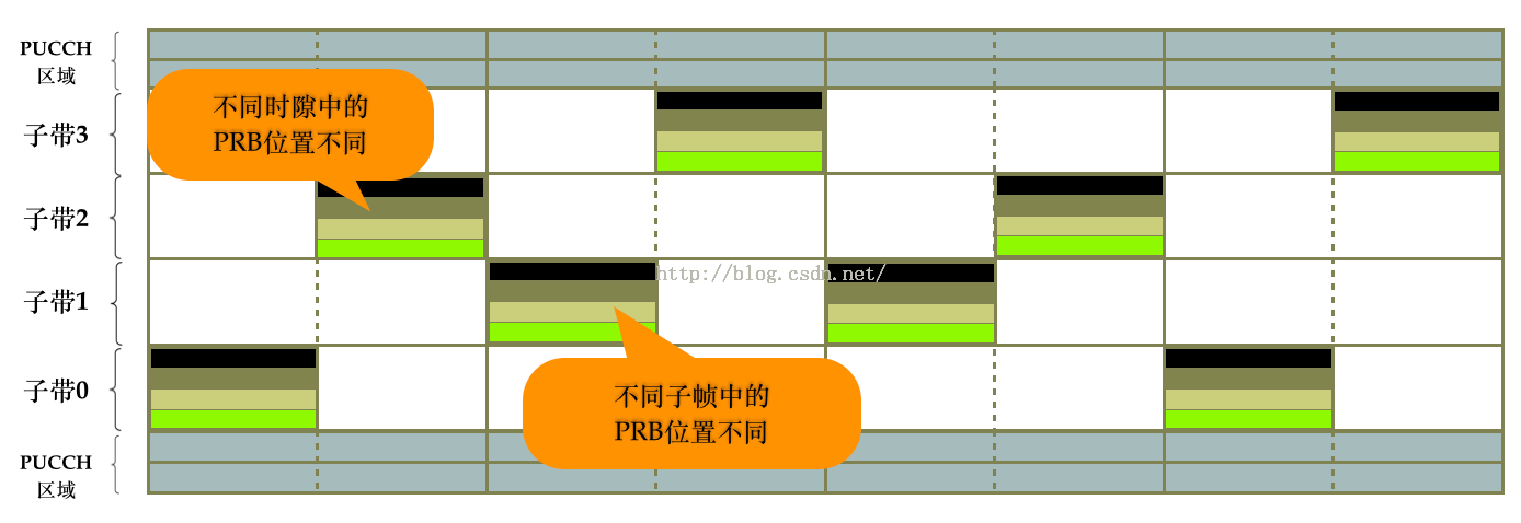
(图5)
上面的这几种跳频方式都可能存在于实际的网络中,如果你只是想了解一下PUSCH跳频的大概内容,那么看到这里就可以了,但如果你是专业的开发人员,马上要进行这方面的代码编写,或者你想更深入的了解这方面的内容,那么就需要继续阅读接下来的内容。因为上面这些跳频图是由下面这些数学公式推导出来的。
3.UE如何判断是否需要进行跳频
在使用数学公式推导PUSCH的PRB跳频位置之前,先介绍下UE是如何判断某个上行子帧是采用跳频还是不跳频的。这里有个总的原则,就是:如果DCI0中的PUSCH跳频比特位(frequency hopping field)被设置为1,那么UE将执行PUSCH频率跳频,否则将不执行跳频。如下图黄色区域标注所示。
如果UE收到了来自eNB的DCI0码流,那么执行跳频的UE,可以通过解析相同传输块最近一次的DCI0码流,来决定子帧n第一个时隙PRB的起始位置。换句话说,如果本次TTI收到了DCI0则按照本次的DCI0解析(对应新传),本次没有收到DCI0但上一次的有,则按照上次的DCI0解析(对应重传)。因为上行RB(无论是VRB还是PRB)是连续的,一旦有了第一个时隙的PRB起始位置,加上DCI中可以解析出的RB个数,就可以知道第一个时隙的所有PRB位置,再根据特定的映射规则(后文将描述这种规则),就可以知道第二个时隙的所有PRB位置
具体来说,UE不是每次发送上行数据都需要DCI0来分配RB资源,比如进行非自适应重传或者上行SPS,或者发送MSG3,这几种场景都不需要eNB通过DCI0分配RB。因此除了上行新传自适应重传这类PDCCH会携带DCI0的场景之外,还有下面这三种不带DCI0的场景需要考虑:
(1)UE执行非自适应重传
这种情况下,虽然eNB并不下发DCI0,但之前新传的时候是有DCI0的,UE只需要查看之前的DCI0中,该TB块对应的VRB是否采用了PUSCH跳频,就知道本次非自适应重传是否需要跳频了:如果上次新传是跳频的,那么本次也需要执行同样的PUSCH跳频规则。
(2)UE发送MSG3
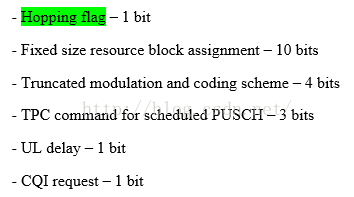
MSG3的资源是由MSG2(或者说RAR)的UL_GRANT下发到UE的,如下图所示。MSG3是否采用跳频,依赖于“Hopping flag”字段:如果该值等于1,则表示MSG3需要执行PUSCH跳频。后面的“Fixed size resource block assignment”字段则包含了具体的RB资源信息,与DCI0的类似。
关于RAR的详细内容,请参考博文《LTE-TDD随机接入过程(3)-RAR(MSG2)以及MSG1的重传》。
(3)UE执行上行SPS
如果相同传输块的PUSCH数据,一开始就是被半持续调度的(关于SPS半持续调度的内容以后再专门写),那么是否跳频就由最近一次半持续调度分配时的DCI0跳频信息决定。
PUSCH有2种类型的跳频方式:Type 1 跳频和Type 2 跳频。这两种方式的不同在于,使用Type1方式则意味着同一个子帧内两个时隙的RB位置是由DCI0码流推导出的,而使用Type2方式则意味着两个时隙的RB位置是按照预定义的模型predefined pattern)进行的,此时整个上行带宽会被分成若干个子带,PUSCH会在几个子带间进行特定规则的跳频,参考上文中的图3~图5。下文将展开讨论PUSCH跳频的规则,提到的DCI0场景,也适用于MSG3的场景。
4.PUSCH跳频方式1(Type 1 PUSCH Hopping
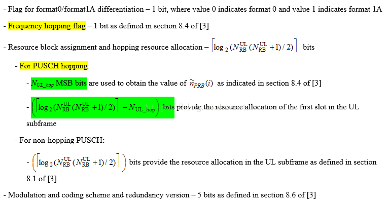
eNB发给UE的DCI0码流中包含了PUSCH跳频的信息,见下面截图中的黄色内容所示:
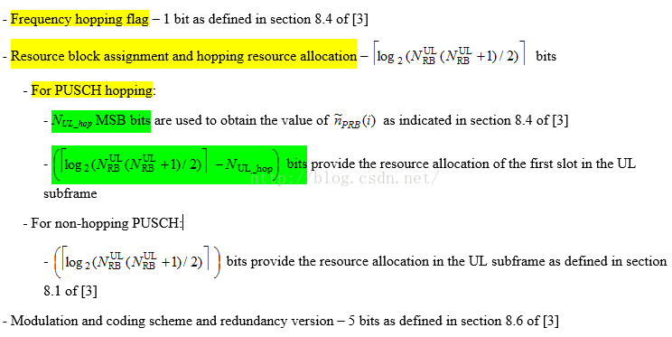
可以看到,对于PUSCH跳频来说,DCI0中携带了2个信息:高位N_UL_hop个比特的跳频信息和低位[ ceil(log2[N_UL_RB * (N_UL_RB + 1) / 2 ])- N_UL_hop ]个比特与第一个时隙RB分配有关的信息。那怎么利用这2个信息来推导两个时隙PRB的位置呢?下面一步步的来拆解分析这个问题,这个过程可能比较抽象,没关系,最后会举个实际的例子说明。
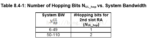
(1)跳频信息占N_UL_hop个比特,这个参数值是由带宽大小决定的,具体见下表。比如10M带宽占用50个RB,则N_UL_hop=2。
(2)如果当前是Type1方式的跳频,则如下图所示,第一个时隙的PRB起始位置用变量n_S1_PRB(i)表示,第二个时隙的PRB起始位置用n_PRB(i)表示。
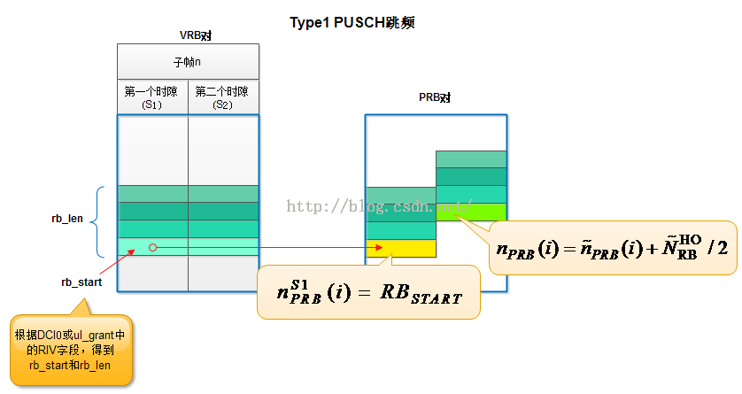
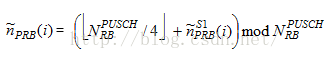
第一个时隙PRB的起始位置等于rb_start,这个值可以从DCI0或UL_GRANT中的RIV字段中直接解码得到,因此接下来的任务主要是解码第二个时隙PRB的起始位置n_PRB(i)。下图是计算第二个时隙PRB起始位置变量n_PRB(i)的过程示意图。从Table8.4-2中可以看到,Nul-hop跳频信息和带宽大小N_UL_RB决定了~n_PRB(i)使用哪个公式以及当前的PUSCH跳频方式(Type1还是Type2)。正如图中的2比特跳频信息NUL_hop=00,此时将选择表格中的公式:
这说明eNB选择的是Type1的PUSCH跳频方式。
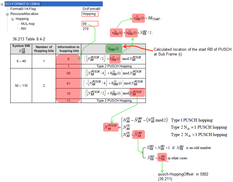
(3)如上图所示,在计算~n_PRB(i)的过程中,最终需要用到两个参数N_HO_RBNsb,这两个参数是由RRC在SIB2中配置的,分别对应信元pusch_HoppingOffset和信元n-SB,见下文的图A所示。
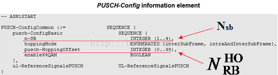
(图A)
至此,就可以知道采用Type1方式跳频后PRB的位置了。以10M带宽为例,如果RRC配置的n-SB=1,pusch-HoppingOffset=4,DCI0中的Nul_hop=00,RIV=270。则:
(A)根据RIV=270可以得到VRB的起始位置rb_start=20,rb_len=6。关于RIV的内容,请参考《LTE-TDD随机接入过程(4)-RIV的解析和Preamble资源的选择》。
(B)pusch-HoppingOffset=4是偶数,所以~N_HO_RB N_HO_RB = usch-HoppingOffset = 4。
(C)Nul_hop=00,所以采用的是Type1的PUSCH跳频,N_PUSCH_RB = N_UL_RB - ~N_HO_RB - (N_UL_RB mod 2) = 50 - 4 - 0 = 46。
(D)第一个时隙PRB的最低位起始位置 n_S1_PRB(i) = rb_start = 20,长度rb_len=6。
(E)~n_S1_PRB(i) = n_S1_PRB(i)  - ~N_HO_RB / 2 = 20 - 4 / 2 = 18。
(F)~n_PRB(i) = ( floor( N_PUSCH_RB / 4) +  ~n_S1_PRB(i) ) mod N_PUSCH_RB = (floor(46 / 4) + 18) mod 46 = 29。
(G)第二个时隙PRB的最低位起始位置 n_PRB(i) = ~n_PRB(i) + ~N_HO_RB / 2 = 29 + 4 / 2 = 31,长度rb_len=6。VRB对与PRB对的映射规则如下图所示。
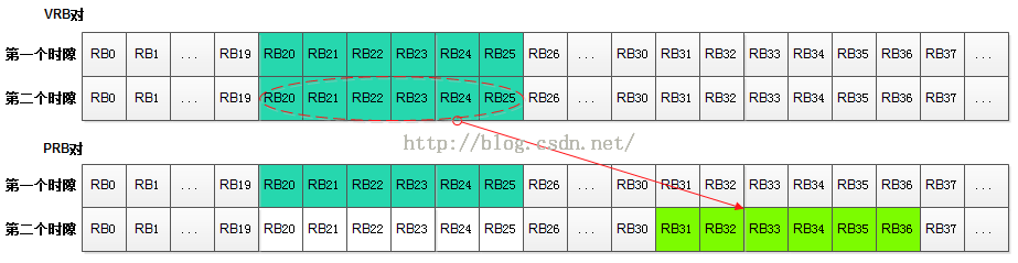
这里对Type1方式的跳频做个总结:在Type1方式中,第一个时隙的PRB位置与不跳频时的PRB位置完全相同,而第二个时隙的PRB位置与第一个时隙相关联
虽然上面计算得到了两个时隙的PRB位置,但UE不是每次都能这么使用PRB资源,协议规定了一个限制条件:当RRC配置的Hopping-mode是“子帧间跳频”(inter subframe)时,那么第一个时隙的资源分配适用于TB块HARQ传输次数为偶数的场景,第二个时隙的资源分配适用于HARQ传输次数为奇数的场景。这是什么意思呢?如果RRC配置的是“子帧间”跳频,则意味着一个子帧内两个时隙的PRB位置必须是相同的,没有频率的相对偏移,类似于前文中的图3所示。每个HARQ进程中的TB块,都有最大HARQ传输次数限制,比如最大可以传输5次,那么第1次、第3次、第5次传输就是奇数次传输,而第2次、第4次就是偶数次传输。即便此时根据公式计算得到两个时隙的PRB位置不同,但对于偶数HARQ传输次数的子帧,两个时隙的PRB均使用第一个时隙的PRB资源分配,而奇数HARQ传输次数的子帧,两个时隙的PRB均使用第二个时隙的PRB资源分配。
参数Hopping-mode是由RRC的SIB2下发到UE的,与参数N_HO_RBNsb在同一个结构体中,见上文的图A,该参数决定了是“子帧间跳频”还是“子帧内和子帧间跳频”。
5.PUSCH跳频方式2(Type 2 PUSCH Hopping
当采用Type2跳频方式时,PRB与VRB的位置关系将按照预定义的模式进行。因篇幅关系,本节内容将放在下一篇博文中继续介绍。
参考文献:
(1)3GPP TS 36.212 V9.4.0 (2011-09) Multiplexing and channel coding
(2)3GPP TS 36.213 V9.3.0 (2010-09) Physical layer procedures
(3)3GPP TS 36.211 V9.1.0 (2010-03) Physical Channels and Modulation 
(4)http://www.sharetechnote.com

Avahi 筆記

Source http://pjack1981.blogspot.com/2012/07/avahi.html

Avahi 筆記

Avahi 是一個在內網內, 用來廣播自己是什麼服務以及用來尋找那些服務的一個工具, 有點像是在一個社區內有個廣播系統, 大家利用他就可以找到郵局在那裡, 醫院在那裡, 而不必事先知道郵局或醫院的名字. 據了解 avahi 是利用 multicast 來做到這件事,安裝上要細分的話可以分成 server 以及 client.


client 的部份主要是用來聽廣播, 得到網路上所有可使用的服務.
?
1
2
3
4
5
6
7
8
9
10
11
12
13
14
15
16
17
18
19
20
21
22
23
24
25
26
27
28
29
30
31
32
33
34
35
36
37
38
39
40
41
42
43
44
45
46
47
pjack@ubuntu:~$ sudo apt-get install avahi-utils
pjack@ubuntu:~$ avahi-browse --help
avahi-browse [options] type>
avahi-browse [options] -a
avahi-browse [options] -D
avahi-browse [options] -b
 
    -h --help            Show this help
    -V --version         Show version
    -D --browse-domains  Browse for browsing domains instead of services
    -a --all             Show all services, regardless of the type
    -d --domain=DOMAIN   The domain to browse in
    -v --verbose         Enable verbose mode
    -t --terminate       Terminate after dumping a more or less complete list
    -c --cache           Terminate after dumping all entries from the cache
    -l --ignore-local    Ignore local services
    -r --resolve         Resolve services found
    -f --no-fail         Don't fail if the daemon is not available
    -p --parsable        Output in parsable format
    -k --no-db-lookup    Don't lookup service types
    -b --dump-db         Dump service type database
 
# 不間斷的聽取廣播內容, 一但有更新就會顯示出來
pjack@ubuntu:~$ avahi-browse -a
+   eth0 IPv6 Virtualization Host centos                    Virtual Machine Manager local
+   eth0 IPv4 Virtualization Host centos                    Virtual Machine Manager local
 
# 你也可以只聽特定的服務, 並且加上 -t 參數, 表示不需要持續的聽廣播
pjack@ubuntu:~$ avahi-browse -t _nodeinfo._tcp
+   eth0 IPv6 bmc-00:26:2d:0a:35:a4                         _nodeinfo._tcp       local
+   eth0 IPv4 bmc-00:26:2d:0a:35:a4                         _nodeinfo._tcp       local
 
 
# 可以再加上 -r, 除了可以獲得該服務的 ip address/hostname 之外,
# 其實有時候該服務也會加上更多有關自己的訊息在 "txt" 欄位
pjack@ubuntu:~$ avahi-browse -r -t _mongodb._tcp
+   eth0 IPv4 db on mongodb-001                              _mongodb._tcp      local
=   eth0 IPv4 db on mongodb-001                              _mongodb._tcp      local
   hostname = [mongodb-001.local]
   address = [172.17.255.33]
   port = [0]
   txt = []
 
# -p 這個參數是把 output 格式變成方便處理一點, 但在舊一點的版本還沒有這個功能
pjack@ubuntu:~$ avahi-browse -r -p -t _mongodb-db._tcp
+;eth0;IPv4;db\032on\032mongodb-001;_mongodb._tcp;local
=;eth0;IPv4;db\032on\032mongodb-001;_mongodb._tcp;local;mongodb-001.local;172.17.255.33;0;


server 的部份主要是要告訴大家你自己是誰, 提供什麼服務
?
1
pjack@ubuntu:~$ sudo apt-get install avahi-daemon

裝好 package 之後, 就可以開始編寫你自己的服務, 預設是放在 /etc/avahi/services 下, 而在 /usr/share/doc/avahi-daemon/examples 裡有一些現成的範例
主要需要設定的
1. service protocol, ipv4/ipv6/all
2. service 名稱,
3. port number
其它細節可以參考這裡
http://manpages.ubuntu.com/manpages/precise/man5/avahi.service.5.html
?
1
2
3
4
5
6
7
8
9
10
 
  "yes">%h</name>
 
  "ipv4">
    <type>_ssh._tcp</type>
    22</port>
  </service>
 
</service-group>

在顯示上不想要顯示 _xxxx._tcp 可以透過設定 /usr/share/avahi/service-types
那就可以讓別人看到 Human readable 的文字
?
1
2
pjack@ubuntu:~$ avahi-browse -t _libvirt._tcp
+   eth0 IPv6 Virtualization Host localhost                 Virtual Machine Manager local

實際應用上, 我曾因為 ipv6 打開的關係造成了一些困擾, 所以如果想要把 ipv6 關掉, 可以在 /etc/avahi/avahi-daemon.conf 內關掉 ipv6. 也可以設定只對那些 interface 發送廣播.
?
1
2
3
4
5
6
7
[server]
#host-name=foo
#domain-name=local
#browse-domains=0pointer.de, zeroconf.org
use-ipv4=yes
use-ipv6=no
allow-interfaces=eth0

因為 avahi 是一個 daemon, 如果想要和這個 daemon 溝通, 可以通過 dbus. 下面是 Python 的範例. 有一次我無法將 avahi-daemon 叫起來, 後來才發現是 dbus 這個 service 死掉了, 一但把 dbus 叫起來之後, avahi 就可以啟動了
http://stackoverflow.com/questions/3430245/how-to-develop-an-avahi-client-server
?
1
2
3
4
pjack@ubuntu:/etc/avahi$ ps aux | grep daemon
102        506  0.0  0.0  23908  1000 ?        Ss   08:48   0:00 dbus-daemon --system --fork --activation=upstart
avahi      523  0.0  0.0  32560  1952 ?        S    08:48   0:00 avahi-daemon: running [wistor.local]
avahi      524  0.0  0.0  32172   472 ?        S    08:48   0:00 avahi-daemon: chroot helper

如果覺得透過 dbus 溝通有點麻煩的話, 也可以直接透過 bash command, 下面是我寫的一個小程式
?
1
2
3
4
5
6
7
8
9
10
11
12
13
14
15
16
17
18
19
20
def _avahi_browse(service):
    output = subprocess.check_output('avahi-browse -r -t %s' % service, shell=True)
 
    node = {}
    nodes = []
    for line in output.splitlines():
        if line.startswith(' '):
            key,value = line.split('=')
            key = key.strip(' ')
            value = value.strip(' []')
            node.update({key:value})
        else:
            if node:
                node['hostname'] = node['hostname'].strip('.local')
                nodes.append(node)
            node = {}
    if node:
        node['hostname'] = node['hostname'].strip('.local')
        nodes.append(node)
    return nodes


最後分享的一個經驗是, 在使用 avahi 要注意的一點就是他為了要降低 loading, 所以更新的速度並不是很快, 一般他都是直接從 cache 裡面抓資料給你, 所以有時你會發現有的服務不存在了, 但從 avahi-browse 還是會看到它, 所以拿到資料後, 你還是要處理有可能服務已經不存在的情況. 不過如果有新的服務加進來, 因為是主動 broadcast, 所以你一定會接到更新. 如果你一定要拿到最新的情況, 目前我已知的方法就只有重啟 avahi-daemon, 比較耗時間.


Reference link:

http://manpages.ubuntu.com/manpages/precise/man5/avahi.service.5.html
http://manpages.ubuntu.com/manpages/precise/man8/avahi-daemon.8.html
http://manpages.ubuntu.com/manpages/precise/man1/avahi-browse.1.html
http://en.gentoo-wiki.com/wiki/Avahi